
Series 1 Intercooler. working well, VIDS on page 11.


Thread Starter
Junior Member
Posts like a Ricer Type-R
Joined: Aug 2002
Posts: 11
Likes: 13

Note to self:
Future intercoolers will require less agressive machining on the LIM opening to prevent fabrication of two block-off plates to add to the bottom of the supercharger.
You'll see what I mean after SC machining later this afternoon/evening (Pacific time). I went max flow, but it'll cost me a little extra work.
Things are REALLY coming together now. Biggest part of the job now is the SC machining, rebuilding, and coating. I also have to use my cars as test vehicles to determine inner core inlet/outlet angles. Both will be turning 'forward' and coming towards the front of the vehicle right after they exit the LIM. Since my tubing is 3/4" INSIDE diameter, and not very flexible, the connections have to be structural as well as 'fluidically functional'. I'm trying very hard to keep this stuff clear of the belt path, and may also fabricate a guard plate just in case I loose a belt.

Senior Member
Posts like a Turbo
Joined: Jul 2005
Posts: 239
Likes: 1
From: Palatine, IL
That looks really awesome!
FWIW - I recently had one of those grey plastic couplers fail on my IC setup. It became deformed and started leaking. The funny thing was it was located behind my headlight on the inlet of my IC pump.
You might be able to find a better threaded barbed coupler here:
http://www.mcmaster.com/
Keep up the good work
Thread Starter
Junior Member
Posts like a Ricer Type-R
Joined: Aug 2002
Posts: 11
Likes: 13
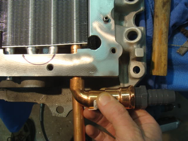
I have brass barbs here at work. I'm using these only because they were free and were included in my front core when I ordered it.
Once the system is up and running, I'll probably go through it and change a buncha stuff. Good machining stuff coming tonight. Stay tuned.
Once the system is up and running, I'll probably go through it and change a buncha stuff. Good machining stuff coming tonight. Stay tuned.

Senior Member
Posts like a Supercharger
Joined: Oct 2006
Posts: 170
Likes: 0
From: Alberta, Canada
Great work, Will. It looks great and should be plenty to give you that pulley drop you're after. Like you said, you can't go much smaller than you already are without machining the snout down (and then you're probably spinning the M62 way too fast anyway). It looks great.
Thread Starter
Junior Member
Posts like a Ricer Type-R
Joined: Aug 2002
Posts: 11
Likes: 13
Ok, where to begin.....
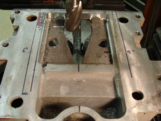
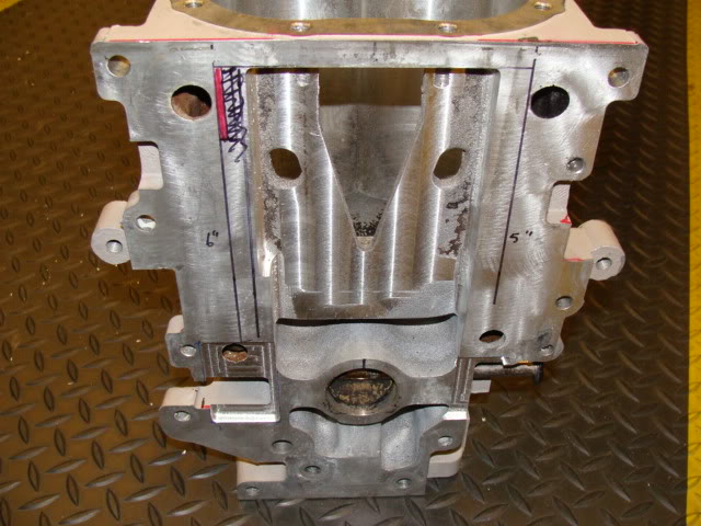
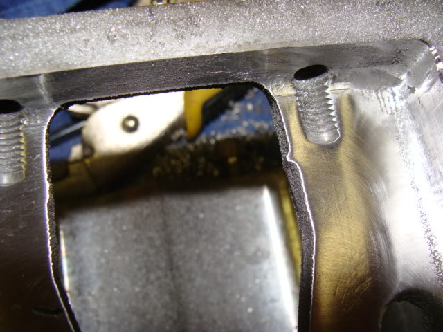
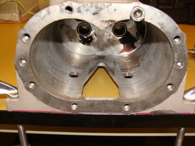
Found some more flaws in the casting. This is the worst LIM and SC I've ever worked on. Both of them. Easily. More work to patch up:
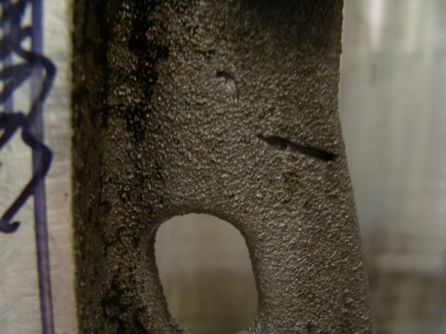
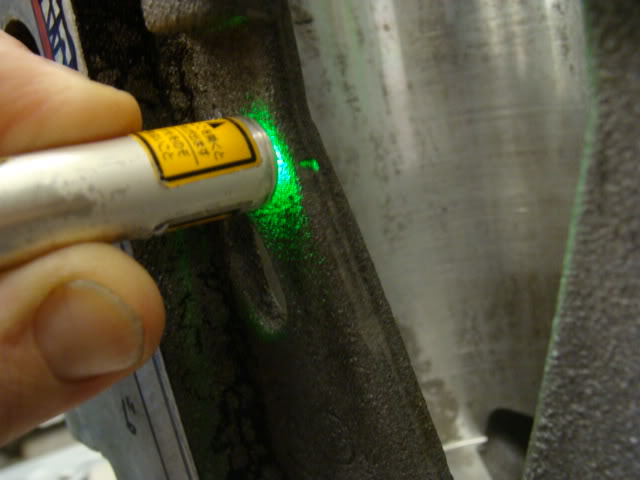
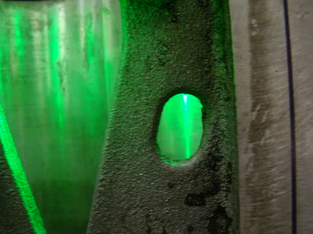
Got a little over-zealous on the LIM milling, and found I'd overlooked two tiny cutouts in the SC that I'd milled enough in the LIM to expose (greyhare spotted it this morning) so we have to get creative (this is why God invented the word 'prototype', and why I have more than one or two manifolds and superchargers laying around here). Some of this goof has to do with PCV flow, so it can't be ignored. Some ports shouldn't be exposed to the LIM cavity, and some should.
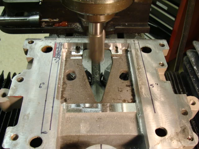
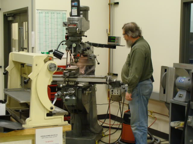
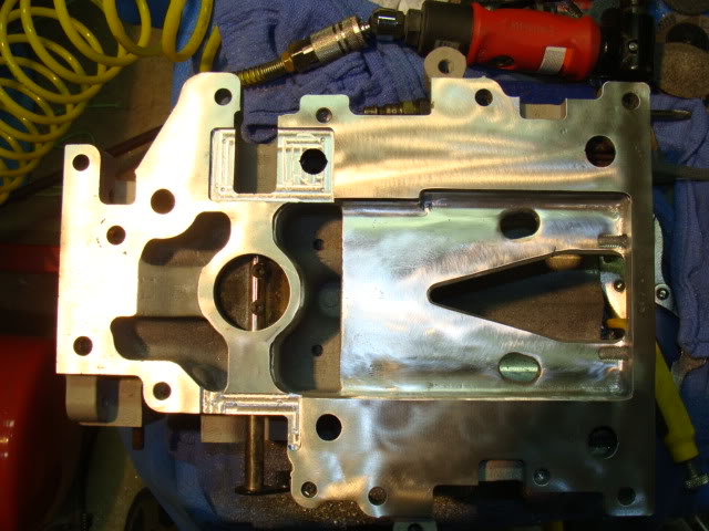
Let the milling begin. Greyhare (Mike) milled the blockoff oops plates while I milled the SC (we had two mills screaming like little girls at a horror movie for a good hour and a half). He also had to do some delicate corner radius work to match my milling on the pockets:
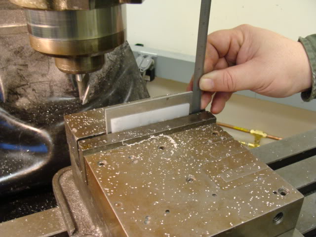
(greyhare deftly dodging blue flaming hot chips from h e l l)
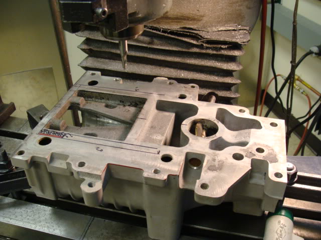
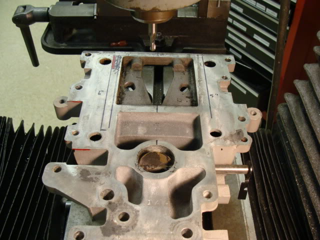
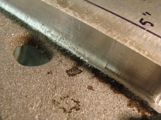
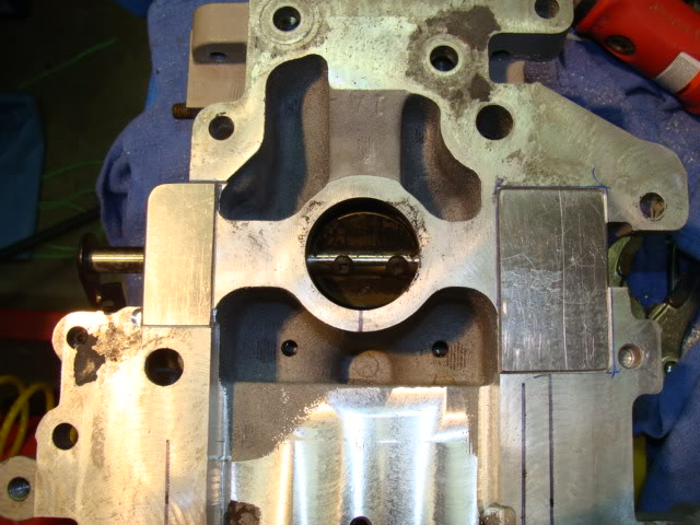
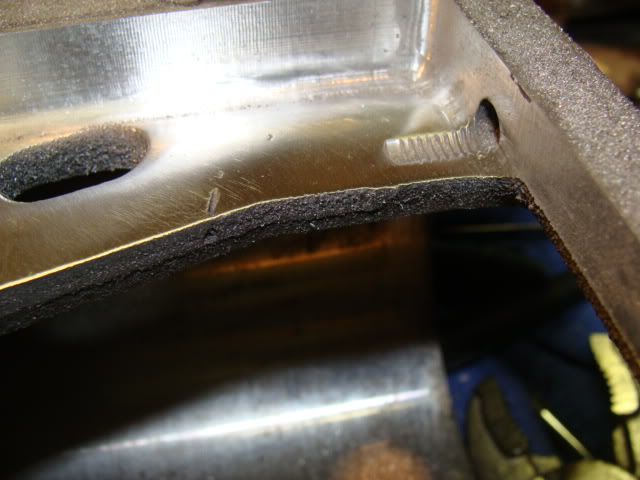
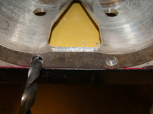
The back to home, roughing in the outlet and other stuff. The proto plug plates are drilled, countersunk, and back-cut. The SC is back-cut in the corners and below the drilled holes in the plates to bind with the JB better:
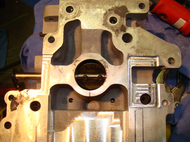
the 'step' you see in my milling on the side is due to internal PCV passages that I really didn't feel like milling into tonight.
Quite a bit of finish work to do. We went out between snowstorms today and figure out on the SLE that the routing of the cooling lines will have to change from the plan drastically. More on that later.
Also learned that this isn't going to be as easy on the S2, which sucks considering the investiment so far, as the S2 manifold is MUCH narrower in that big open area between the ports. I can get a much wider core in there than them, but shorter in length.
The other unfortunate part is that while my goal was to make this possible for at least a few S1 L67 owners here, the practicality isn't there. Mine will work, but there'* alot more custom work involved than I'd originally hoped. I hope at least one more S1 tries this, and a S2 or two also.
Found some more flaws in the casting. This is the worst LIM and SC I've ever worked on. Both of them. Easily. More work to patch up:
Got a little over-zealous on the LIM milling, and found I'd overlooked two tiny cutouts in the SC that I'd milled enough in the LIM to expose (greyhare spotted it this morning) so we have to get creative (this is why God invented the word 'prototype', and why I have more than one or two manifolds and superchargers laying around here). Some of this goof has to do with PCV flow, so it can't be ignored. Some ports shouldn't be exposed to the LIM cavity, and some should.
Let the milling begin. Greyhare (Mike) milled the blockoff oops plates while I milled the SC (we had two mills screaming like little girls at a horror movie for a good hour and a half). He also had to do some delicate corner radius work to match my milling on the pockets:
(greyhare deftly dodging blue flaming hot chips from h e l l)
The back to home, roughing in the outlet and other stuff. The proto plug plates are drilled, countersunk, and back-cut. The SC is back-cut in the corners and below the drilled holes in the plates to bind with the JB better:
the 'step' you see in my milling on the side is due to internal PCV passages that I really didn't feel like milling into tonight.
Quite a bit of finish work to do. We went out between snowstorms today and figure out on the SLE that the routing of the cooling lines will have to change from the plan drastically. More on that later.
Also learned that this isn't going to be as easy on the S2, which sucks considering the investiment so far, as the S2 manifold is MUCH narrower in that big open area between the ports. I can get a much wider core in there than them, but shorter in length.
The other unfortunate part is that while my goal was to make this possible for at least a few S1 L67 owners here, the practicality isn't there. Mine will work, but there'* alot more custom work involved than I'd originally hoped. I hope at least one more S1 tries this, and a S2 or two also.
Thread Starter
Junior Member
Posts like a Ricer Type-R
Joined: Aug 2002
Posts: 11
Likes: 13
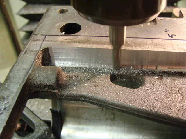
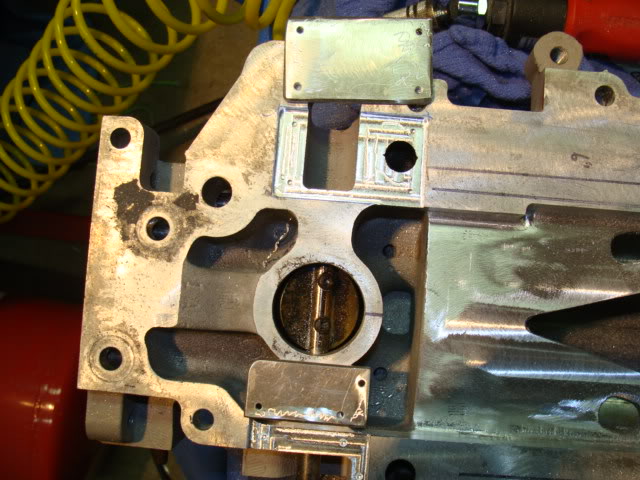
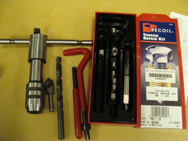
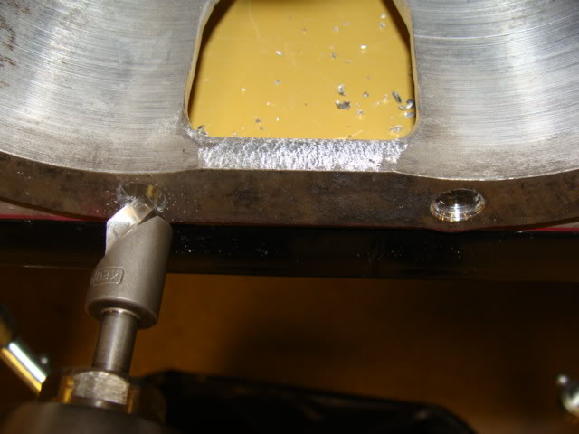
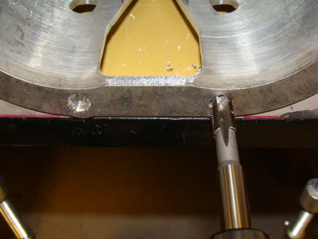
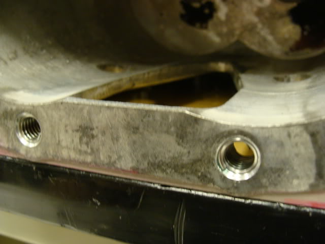
Did a little more work this morning on the blankoff plates, and got my heli-coil thread inserts into the two lower holes where I machined off the threaded bosses to strengthen what is now shorter threads:
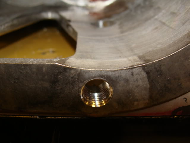
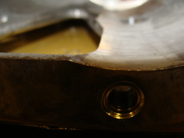
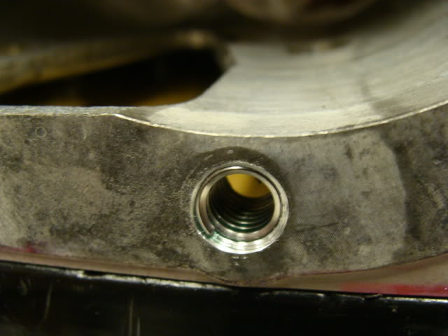
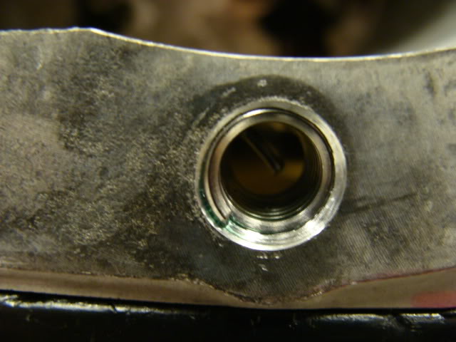
(tab is broken off now)
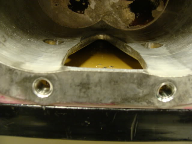
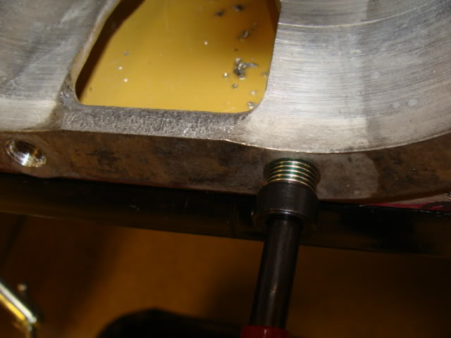
And the blankoff plates nearly done:
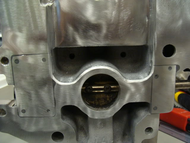
(tab is broken off now)
And the blankoff plates nearly done:

Senior Member
Posts like a 4 Banger
Joined: Mar 2007
Posts: 149
Likes: 0
From: portland
The amount of effort and thought you are exibiting is staggering. Give me an idea of how many Times since last Friday you have torn down a motor past the LIM? The only real question I ve got is there going to be a Significant loss in cooling due to airflow obstruction and residual heat from the IC radiator placement? Forgive me if You have already covered that.
Thread Starter
Junior Member
Posts like a Ricer Type-R
Joined: Aug 2002
Posts: 11
Likes: 13
The core flows nearly 3 times the natural area of the supercharger outlet. That was calculated before I purchased this particular heat exchanger.
There will be no residual heat from the front radiator. The ratio in size between the two heat exhangers is * large, that the water will be at ambient temps before the water leaves the front radiator to go back to the LIM exchanger. My bench testing also proved this.
I've torn zero motors down since last friday. This hasn't been on a car yet, but will be VERY soon now that I know it works, and it works better than I expected.