When you click on links to various merchants on this site and make a purchase, this can result in this site earning a commission. Affiliate programs and affiliations include, but are not limited to, the eBay Partner Network.
carfixer007, I'd appreciate any information you can give me. I was hoping it was not the transaxle - hopefully I did the solenoid test correctly and it is not the solenoid - and if it isn't the transaxle I was assuming that leaves electrical.
Did you also check for power and ground in the harness connector? When testing solenoid circuits, I like to use Test lights rather than voltmeters, because it shows working voltage vs potential voltage......A voltmeter will not show a drop in voltage due to a bad connection in another part of the same circuit....
With transmission harness disconnected, and ignition "on", check for power and ground with the test light at terminals E and A(sol A) and E and B(sol B) of the harness connector.........Both solenoids are powered in Park with ignition on by the PCM/ECM, by grounding each solenoid electronically..........
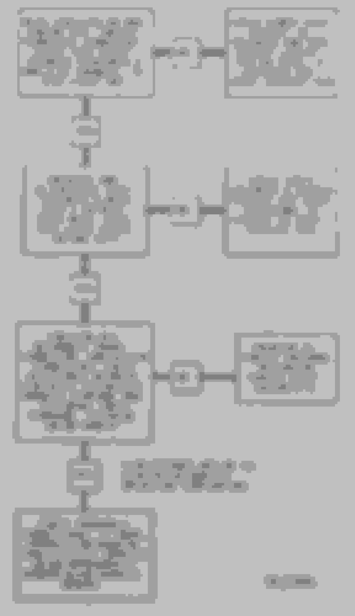
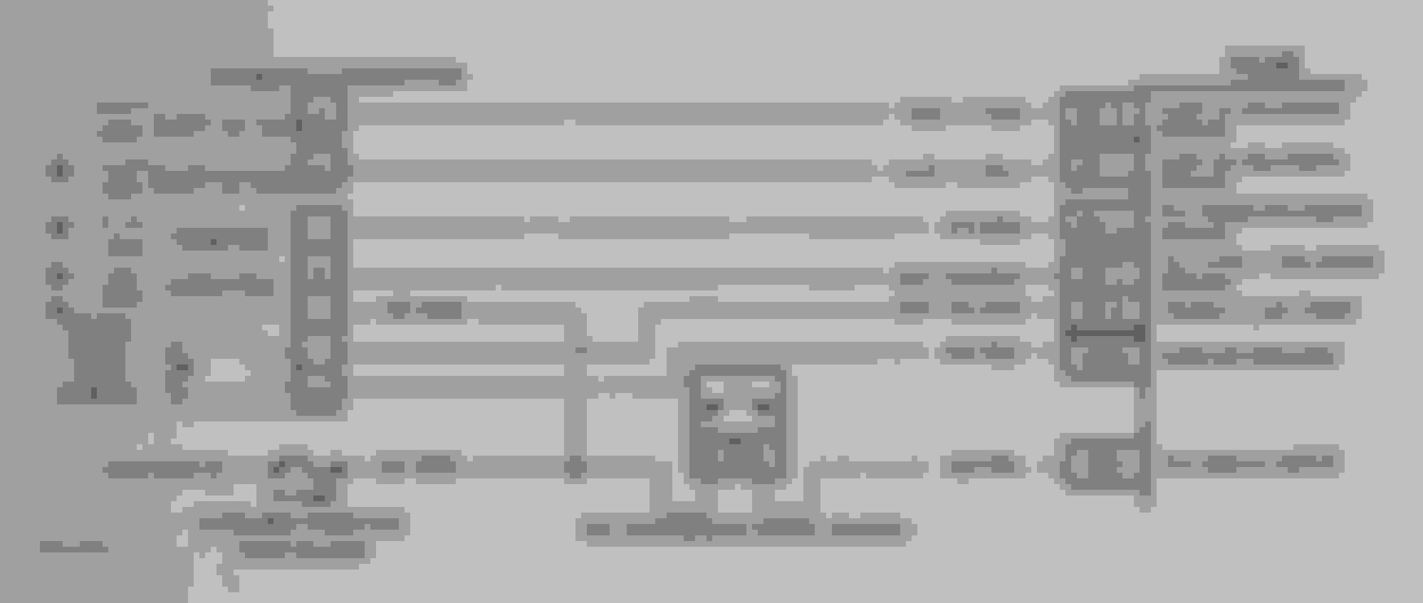
OK. Here'* the flow chart and an easier to read diagram of the circuits for the transaxle. Glean what you can from it and do your tests once you have a good idea of the circuit. The thing I would concentrate on right now is continuity of the circuit.
A little thought problem. Do we need to check the ground side? If so, why? If not, why no
t?
carfixer007, thanks for the info.
I am ok in conducting the first step test.
I am not sure what the second step, "Energize and De-energize shift solenoid b with tech 1 in misc. tests mode." means or how to do it.
If I can find the PCM, and then identify the BE15 pin then I can do test 3. (I guess the BE is the same BE as on the connector but that doesn't tell me which PCM pin it is. But, I may just not understand what the test is saying.)
I think what step 4 is saying is just to check the transaxle connector and ensure it is not broken or shorted - basically that the connector is good.
I definitely think the ground should be checked, especially if everything else seems to be ok but still in limp mode. I'll do research on how to check the ground for shorts. From what Tech II said just above, it appears to me that when the ignition is turned on the ground circuit (-) is closed to complete the circuit. That would indicate if I am correct, that the (+) is always there - waiting for the ground.
FWIW...The nomenclature for your module is ECM and not PCM. Just so we are on the same page. They mean the same thing it'* just that ECM is OBDI and PCM is OBDII and the use of a Tech I scan tool in the second test tells me it'* still an OBDI. Blah, blah.
You did good on the thought problem.
The B+ would be effecting all devises, except the temperature sensor, if it were missing. The only way the B+ would be having an issue with only the B solenoid is if it were a problem with the internal wiring of the transaxle which is highly unlikely,
The first thing I suggest you do is check the ground from ECM to transaxle.
Key On Engine Off. Connect the black lead of your test light or meter to a good ground and the other to 'B' on the HARNESS and see if it'* getting ground. It may be the transistor which drives the ground for the solenoid is bad. The reason I suggest this test first is experience. This is a common problem with this series of GM ECM'*. While you are there also check the 'A' solenoid for ground. Once you have identified the two pins it should be quick to jump from the one to the other. If it passes this test we will dig further. If it fails this test which is more likely than not we have identified the problem. ECM
Let us know what you find.
Carfixer, connecting one end of a test light to a ground and the other end to another ground at terminal B is going to prove what? You are connecting a test light to two grounds.....You want to connect one end to term E, power, and the other end to terminal B to see if the test light lights......if it doesn't, you either have an open in the wire between the harness a connector at term B and the ECM, or a a bad ECM.....
You test sol A by attaching to E and A....the test light should light...
THANKS....Brain fade again. I need to take a break. Make that a nap. Didn't get much sleep last night. I will be back tonight.
On the connector, I think E (at 12 o'clock) is the + common, G (at 8 o'clock) is the - common (don't know if common is the correct term or not but both from battery), C (+) is at 10 o'clock, B (+) is at 7 o'clock, A (+) is at 5 o'clock, F (I THINK THIS SHOULD BE NEGATIVE) is at 4 o'clock, and D (+) is at 2 o'clock.
With the key at on, the test light illuminates at every position I expect: E - G, G - C, G - B, G - A, G - D AND from G - F which I don't think should illuminate as from what I see both G and F are negative.
If I am correct in that, a positive charge is getting on either G or F somewhere.
Carfixer, connecting one end of a test light to a ground and the other end to another ground at terminal B is going to prove what? You are connecting a test light to two grounds.....You want to connect one end to term E, power, and the other end to terminal B to see if the test light lights......if it doesn't, you either have an open in the wire between the harness a connector at term B and the ECM, or a a bad ECM.....
You test sol A by attaching to E and A....the test light should light...
I did the test as you stated, E to A and E to B, also. Neither one illuminated. However, in looking at the diagram provided by carfixer007, I just don't follow what you are saying. As I understand the diagram, G and F are both negative and all of the rest are positive. I'm lost when E to B or E to A should illuminate because they both appear to be + to me.