
1999 buick limited

Senior Member


True Car Nut
Joined: Jun 2011
Posts: 3,493
Likes: 613
From: VA


When it comes to AC units I am as confused as you, I know a tiny amount, hopefully Tech II can suggest what circuits to test, or how to see if the control unit is bad.
A few lines have vacuum, so I am pretty sure that is a good thing.
I can only guess control unit, actuator/blend door.
Hopefully somebody can help you get it figured out soon.
A few lines have vacuum, so I am pretty sure that is a good thing.
I can only guess control unit, actuator/blend door.
Hopefully somebody can help you get it figured out soon.
Senior Member
True Car Nut
Joined: Jun 2003
Posts: 7,270
Likes: 465
From: Las Cruces, NM
FSM is Factory Service Manual. Mine has diagrams for not only the flappy doors, but also has a table for which modes should have vacuum at which locations.
I may have to dig it up to see if it would be any help, but I am doubtful given the two cars are 6 years apart, with '99 also being a bit of a transition year on some things too.
I may have to dig it up to see if it would be any help, but I am doubtful given the two cars are 6 years apart, with '99 also being a bit of a transition year on some things too.
Senior Member

True Car Nut
Joined: Feb 2014
Posts: 2,878
Likes: 1,097
From: Worcester, Ma.
Hopefully this helps....
The orange line is the recirc valve.....normally, outside air comes into the HVAC module, and is distributed throughout the ductwork.......however, if a dedicated recirc button is pushed, or if A/C MAX is pushed, circuit #1395 is energized, and the solenoid provides vac to the orange line to the recirc actuator, closing outside air.......
What the defrost actuator does, is either sends air flow to the defrost outlet, or to the vent registers in the I/P panel.....when circuit #1396 is energized the solenoid provides vac to the blue line to the defrost actuator, and this, closes the "channel" to the defrost outlet, and opens the channel to the vent registers......when it is de-energized, vac is lost, then the defrost channel is opened and the vent channel is closed....
Now the Bi-Level actuator, which I will call BL......it has three positions.....the at rest position, where it gets no vacuum.....this sends air flow through two channels, the floor AND the vent/defrost channel(this channel is controlled by the defrost actuator, as previously mentioned).....the second position is the heat position, here circuit #1397 is energized and vac is sent to the white line to the BL actuator.......this closes the vent/defrost channel, and leaves the floor channel open.......the third position is the vent position, where circuit#1394 is energized and this causes vac to flow through the green line to the opposite side of the BL actuator......this closes flow to the heater channel, and leaves the vent/defrost channel open(once again the air flow in this channel is controlled by the defrost actuator)......
So if you want flow out of the floor ducts, the white line will get vacuum....
If you want flow out of the vents in the I/P, then the green line will be energized and also the blue line.....
For defrost only, the green line only gets vacuum......for defrost and heater, there will be no vac to any line......
For bi-level(floor and vent), the blue will get vacuum....
So, as far as your test goes.......
Today 07:23 PM - permalinkcliff
Attached a jumper line from where the purple vacuum tube is connected to the orange splice by the top of the programmer box, to the male nipple that corresponds to the purple line on the programmer box, I also attached 4 clear plastic tubes to the other male nipples (GREEN, WHITE, ORANGE, BLUE) which are the same color and position on the clear plastic harness, I started the car with the control panel (head) in the off position, I got vacuum to the white#4 nipple,
In the off position, I would think none of the solenoid valves would be energized, UNLESS, the control head remembers the last known mode command .....
I turned the air flow button to FLOOR,MID and got vacuum to the blue #6 nipple,
That is correct......air flow should go to the floor duct and also the vent duct....
I then switched to the Mid air flow and got vacuum to the blue#6 and green#3 nipple,
That is correct.....with just air flow from the vents....
I switched to the FLOOR air flow and got vacuum to the white nipple #4 But had air to the defroster,
Yes you should have vac at the white, and there should be strong air flow at the floor duct and little flow to the defroster.....this sounds like a problem with the BL vac actuator....
I switched to WINDSHIELD FLOOR air flow and got NO vacuum at any tube but had air to the floor and windshield
That is correct also......

Thread Starter
Senior Member
Posts like a Turbo
Joined: Mar 2011
Posts: 231
Likes: 25
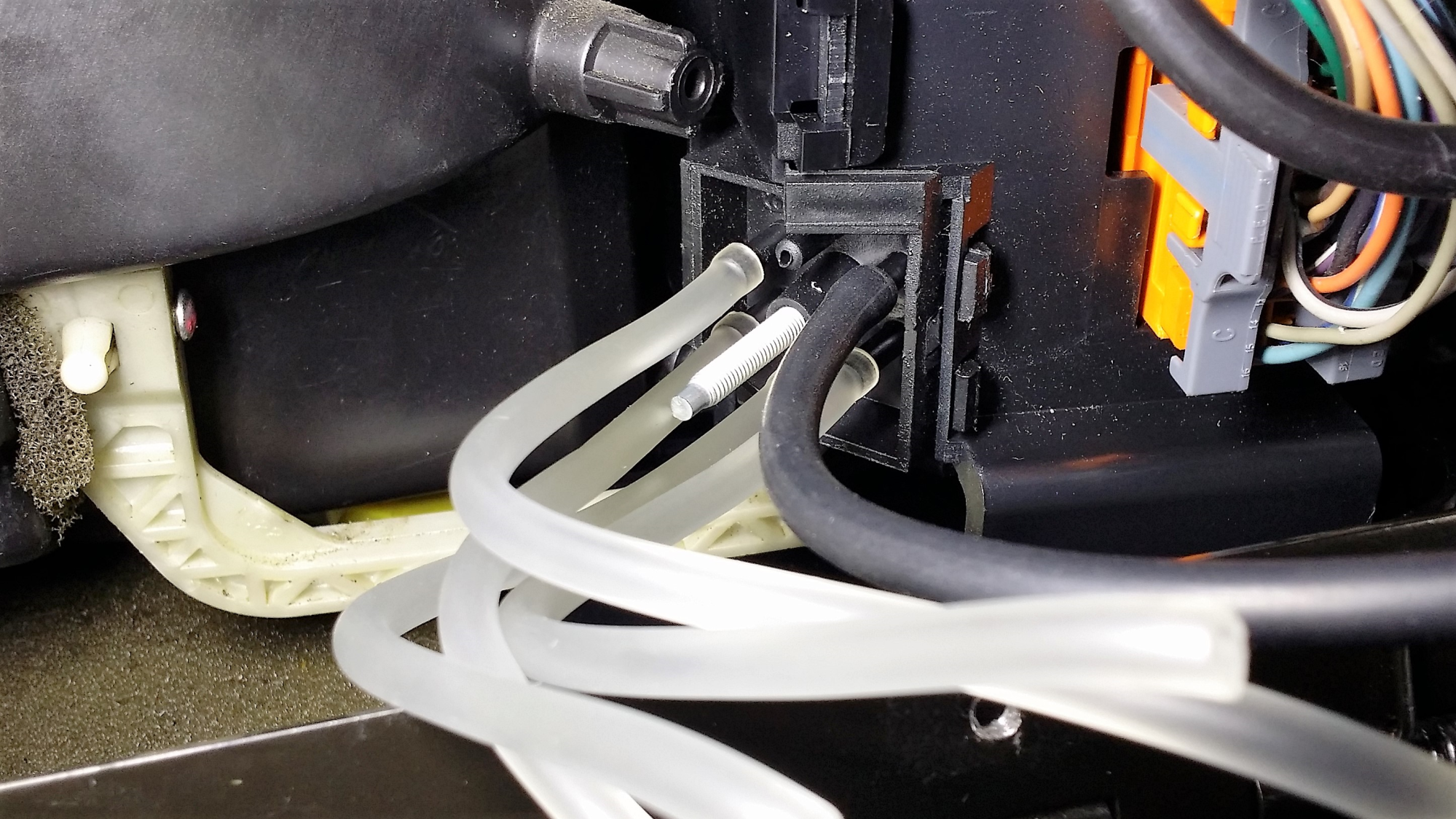
in this picture I attached 4 white tubes to the nipples on the programmer and a black tube to the vacuum line that has an orange splice
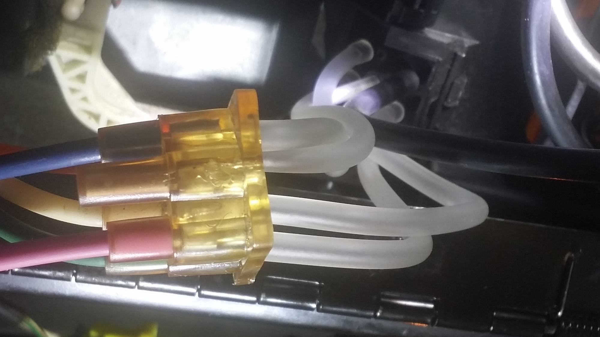
picture #2
here is one for the books ----- after installing the new programmer, nothing was working, Tech II suggested to see if I was getting vacuum to the other nipples, I cut some tubing and put them on the programmer started the car and checked to see if I was getting vacuum when I would switch to the different modes on the display on the control panel, I was getting vacuum, very good, so I took off the tubing and the black tube and put the harness on the programmer and hooked up the purple tube back on the orange splice, started the car and turned on the control panel, NOTHING, Tech II had mentioned a green and white tube that went to the bi level actuator, I got under the dash and found the green and white tubes, took them off the actuator( they both go to the same actuator) and tested to see if I got vacuum when I started the car, NOTHING in any mode on the display, so I said to myself, why not hook up the tubes directly from the programmer, took off the clear harness from the programmer, reinstalled the white tubes and the black tube on the nipples to the programmer and took those tubes and hooked them directly to the clear harness as in picture #2, started the car and wonders of wonders, everything works just fine, turns out I was nor getting a good seal on the clear harness and the programmer, son of a biscuit eater.....