
Illustrated rebuilding of a L36 into a supercharged 3800...

Senior Member
True Car Nut
Joined: Feb 2003
Posts: 4,508
Likes: 2
From: Philly

Originally Posted by clm2112
No, they are the same basic short block regardless of FWD vs RWD use. They both are based on the same block casting. Only differences are between the L67 rotating assembly and the L36 rotating assembly. I thought that the Camshaft grinds might be different, but every place I have looked up replacement cams lists the same Melling MC1292 roller cam as a replacement for both N/A FWD and RWD motors..as well as the */C L67. If someone cares to look up GM part numbers and post them, that would be great.

Thread Starter
Junior Member
Joined: May 2006
Posts: 0
Likes: 0
From: BonnevilleHell
Originally Posted by 95naSTA
I just wanted to add that the cams are the same. But, the timing cain gears for both are are slightly different and the L67 cam is retarted a few degrees compared to the L36'*.
Thread Starter
Junior Member
Joined: May 2006
Posts: 0
Likes: 0
From: BonnevilleHell
Well, hit another little snag in the assembly. A whole bunch of parts showed up today. Got the four needed head bolts to finish off the 2-4-6 cylinder bank. Also got the torque axis mount casting, spacers, and studs. That'* where the snag comes in.
Since the motor that provided the brackets was a Grand Prix, the motor looks just like the photo from GM...with the torque mounts comming off the cylinder heads towards the radiator support. The belt routing on the front of the motor is different and precludes the use of the torque axis mount.
So now the search is on for a set of brackets from a 1997 Bonneville with the torque axis mounts to finish dressing up the front of the motor. I could still finish the motor and install it without the torque axis mount, but that means changing out the accessory belt setup later. (It would be a heck of a lot easier to get it done now, before the motor goes into the car)
Thread Starter
Junior Member
Joined: May 2006
Posts: 0
Likes: 0
From: BonnevilleHell
Oil Pan Spotting....
Since we were talking about oil pans and the differences between series II FWD and RWD motors, here'* some illustrations to help you out.
Here'* the oil pan being used on this Series II L67 (FWD L36 is the identical pan)


Ok, Now this is what a Series II Rear Wheel Drive pan looks like

And finally, while it is tempting to try to use an older Series I pan, here'* some differences that will screw you up:
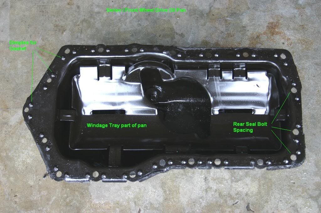

Hope that clarifies that a little
Since we were talking about oil pans and the differences between series II FWD and RWD motors, here'* some illustrations to help you out.
Here'* the oil pan being used on this Series II L67 (FWD L36 is the identical pan)
Ok, Now this is what a Series II Rear Wheel Drive pan looks like
And finally, while it is tempting to try to use an older Series I pan, here'* some differences that will screw you up:
Hope that clarifies that a little
Guest
Posts: n/a
Keep it coming with the great info Curt 
__________________
Best Car Insurance | Auto Protection Today | FREE Trade-In Quote
__________________
Best Car Insurance | Auto Protection Today | FREE Trade-In Quote
Thread Starter
Junior Member
Joined: May 2006
Posts: 0
Likes: 0
From: BonnevilleHell
Installing the Oil Pan:
First up is the oil pickup tube and screen. It installs with two 1/4"-20 tpi, 3/4" long bolts. There'* a paper gasket between the pickup tube and the block (don't forget it) and torque to 11 ft-lbs

Next up, the windage tray/oil pan gasket. On this one, I smeared a dab of RTV at the seam between the timing cover and the block. Then slipped in the gasket/windage tray.

And finally, the oil pan. There are twenty 1/4"-20 tpi x 1" bolts. Put them all in loose, then go around and tighten them down. Oil pans are flexible, so you need all the bolts in first to line the pan up before you start tightening them down. That will pull the pan into shape. This pan was a little twisted. The bottom of it had been dented in. I hammered the dents out with a mallet and a block of wood before cleaning and repainting the pan.

That leaves the drain plug (with new rubber washer) and a pipe plug to seal up the oil level sender bung (I don't have the wiring to support this feature, so I'll just plug the hole in the pan.)
First up is the oil pickup tube and screen. It installs with two 1/4"-20 tpi, 3/4" long bolts. There'* a paper gasket between the pickup tube and the block (don't forget it) and torque to 11 ft-lbs
Next up, the windage tray/oil pan gasket. On this one, I smeared a dab of RTV at the seam between the timing cover and the block. Then slipped in the gasket/windage tray.
And finally, the oil pan. There are twenty 1/4"-20 tpi x 1" bolts. Put them all in loose, then go around and tighten them down. Oil pans are flexible, so you need all the bolts in first to line the pan up before you start tightening them down. That will pull the pan into shape. This pan was a little twisted. The bottom of it had been dented in. I hammered the dents out with a mallet and a block of wood before cleaning and repainting the pan.
That leaves the drain plug (with new rubber washer) and a pipe plug to seal up the oil level sender bung (I don't have the wiring to support this feature, so I'll just plug the hole in the pan.)

Thread Starter
Junior Member
Joined: May 2006
Posts: 0
Likes: 0
From: BonnevilleHell
More stuff going on. Idler Pulley and the Torque Axis mounting. Note, apply sealant to bolts and studs, some of them extend into the water jackets.

Front view of the motor with the Torque Axis mount in place. For the moment, it'* just loosely installed. Once all the other accessories and belts are in place, I'll install it for real.

Moving over to the left side of the engine, I can hang the exhaust header on.

And finish it off with the lift ring and heat shield.

If the heat shield looks a little funny, well, it is. I didn't know it till now, but the Bonneville and Grand Prix manifolds are slightly different with respect to the collector placement. Note the manifold in the photo has the collector right below the #4 cylinder exhaust port. On the Grand Prix that donated the heat shield, the collector is between the #4 and #6 exhaust ports. Surprise!
I cut the heat shield to get it to fit. I'll probably get a replacement heat shield before the motor gets installed.
Also, there'* a modification to the header that is not standard. The EGR pipe on #6 and the extra header flange have been removed. The car will not be using EGR, so I had the tube lopped off and welded closed.
Front view of the motor with the Torque Axis mount in place. For the moment, it'* just loosely installed. Once all the other accessories and belts are in place, I'll install it for real.
Moving over to the left side of the engine, I can hang the exhaust header on.
And finish it off with the lift ring and heat shield.
If the heat shield looks a little funny, well, it is. I didn't know it till now, but the Bonneville and Grand Prix manifolds are slightly different with respect to the collector placement. Note the manifold in the photo has the collector right below the #4 cylinder exhaust port. On the Grand Prix that donated the heat shield, the collector is between the #4 and #6 exhaust ports. Surprise!
I cut the heat shield to get it to fit. I'll probably get a replacement heat shield before the motor gets installed.
Also, there'* a modification to the header that is not standard. The EGR pipe on #6 and the extra header flange have been removed. The car will not be using EGR, so I had the tube lopped off and welded closed.
Senior Member
True Car Nut
Joined: Feb 2003
Posts: 4,508
Likes: 2
From: Philly
Thats interesting.
That oil pickup looks different from the one on my 95 and the one in my spare parts bin. There is nothing shrouding the screen with a hole in it. Its just the screen
That oil pickup looks different from the one on my 95 and the one in my spare parts bin. There is nothing shrouding the screen with a hole in it. Its just the screen
Thread Starter
Junior Member
Joined: May 2006
Posts: 0
Likes: 0
From: BonnevilleHell
Originally Posted by 95naSTA
That oil pickup looks different from the one on my 95 and the one in my spare parts bin.
Some more stuff going on. The intake manifold gasket surfaces are cleaned to a inch of their lives with acetone to remove any oil on the surfaces.

Next, I applied beads of RTV on both ends of the valley and also around the coolant passeges coming out the heads. ( This isn't the way you are supposed to do it, but with all the coolant failures that are happening, I'm going to deviate and try to take extra steps to seal the manifold up.)

Next on, the intake gaskets and more RTV. On the manifold valley gaskets, there'* is only one gasket type supplied in the kit. You must trim off one leg on each gasket to get them to fit properly to the block.

Now the intake manifold goes on with the twelve 5/16" - 18 tpi x 1.25" bolts. When installing them with a lot of RTV, get all the bolts in loose, then start snugging them down in a criss-cross pattern (working from the middle four towards the ends.) Don't be in a big hurry, just keep repeating the pattern till they are all hand tight. Then torque to 11 ft-lbs in the same criss-cross pattern.

Once the manifold is on, I need to install the locating dowel pins for the supercharger. They are pressed into the counter bores on two of the SC bolts. Here, I'm using a bolt and a stack of washers to press one of them into the manifold.

And last, on goes the supercharger with it'* gaskets and O-rings.

Time to take a break and start fabricating a few items I'll need to finish this. (These are items that are caused by the motor going into a 1990 Bonneville.)