
4th Engine coming up- L36 to L67 Swap

Senior Member
True Car Nut
Joined: Dec 2009
Posts: 9,616
Likes: 594
From: western,ny state


for research reasons;
The CS terminals are designated as follows:
P-Terminal: The Pulse/Phase terminal can provide a 12V square wave to determine alternator speed, used by some Electronic Control Modules or vehicle computers. Connects to the stator. Some ICU’* monitor this signal and adjust engine parameters accordingly.
L-Terminal: This terminal is connected to the “Low” side of the warning lamp, with the lamp’* “High” side being fed by the ignition circuit. Some regulators require a 35-ohm resistance inline with this circuit if no lamp is used otherwise alternator damage may ensue. Some applications have a resistor connected in parallel to the lamp in case the lamp bulb opens up and burns out. The resistor will be there to provide a path for current and voltage. Some vehicles supply a 5Vdc reference to this terminal from their ECU or Computer; other vehicles don’t, so be aware of the various models of regulators. Other regulators may be tested by application of a 50-Ohm pull-up resistor to connect the L-Terminal to the 12Vdc source, I believe that any resistance between 35 Ohms (5-Watt resistor) and 500 Ohms (1/2 Watt resistor) can be used safely.
F/I-terminal: has several duties depending on the specific regulator, some regulators have a resistor that is internally connected between the Field and Lamp terminal. Other regulators use the F/I terminal to provide field duty cycle information to the vehicles Electronic Control Module or computer. These regulators are not interchangeable, but for our Jeeps, it hardly matters. For ECM related vehicles it can be of paramount importance. If the alternator that is selected comes from a vehicle that only uses the I-Terminal then the wiring may simply require a wire from an ignition source in order for the alternator to operate correctly.
*-terminal: This is a heavier gauge terminal spade lug that is connected to the battery. This terminal is the “Sense” circuit and monitors battery charge. The *-terminal on the CS-130 regulator is larger than the other three terminals.
The CS-130D Alternators have the following connections…NOTE: All of the Terminals on the CS-130D regulators are the same size.
P-Terminal: Provides a 12Vdc square wave as in the CS-130 application.
F/I-Terminal: It gets a bit tricky here, as some applications do not incorporate a lamp circuit. In vehicle applications of the “no lamp” kind, this terminal is connected to the Ignition Switch, and an internal resistor is used to limit current and voltage. Other regulators use this terminal as an output and refer to this pin as a Field Terminal, as such, it provides an output that is proportional to the field duty cycle of the alternator to an a vehicles ECM. The ECM now has an input to sense alternator loading and engine loading, and can increase/decrease engine speed accordingly. Here is an important consideration, since the regulators on CS-130D type alternators have these two different types of regulators (F-Type or I-Type) they cannot be interchanged. I-Type regulators use the F/I-Terminal as an input and this can simply be an ignition source 12Vdc voltage that the alternator uses; F-Type regulators use the F/I-Terminal as an output (this ion is a signal that is provided to the vehicle computer and the computer uses it to monitor the field intensity of the alternator as an input. If you supply a 12Vdc signal to this input, you may very well ruin the alternators regulator.
L-Terminal: This is the lamp terminal and operates in the same manner as the CS-130 lamp circuit above. It is of interest to note that some applications use the ECM to send the L-Terminal a signal (5Vdc reference), and the F-Terminal responds with a signal sent to the ECM, in this application the ECM and the Regulator form a “closed loop” to control engine loading and alternator output.
*-Terminal: This is the “Sense” terminal and is connected to the battery. It senses the voltage level of the battery and feeds the regulator circuit this reference so that the regulator can adjust the Pulse Width Modulation to control the alternators output. The *-terminal on the CS-130D regulator is the same size as the other three terminals, unlike that of the CS-130.
Senior Member
True Car Nut
Joined: Dec 2009
Posts: 9,616
Likes: 594
From: western,ny state

Thread Starter
Retired
Certified Car Nut
Joined: Jul 2003
Posts: 17,960
Likes: 1,839
From: Dark Side, AZ
Ok, got another one.
Looking at the alldata schematics for the L36 PCM, I am seeing on the Blue connector PIN 30-EVAP PURGE VALVE CONTROL. On my car, this valve is located on top of the charcoal canister behind the drivers side headlight.
For the L67, It is PIN 66 EVAP VACUUM SWITCH(VIN 1 ONLY), and according to this picture, it is located behind the supercharger.
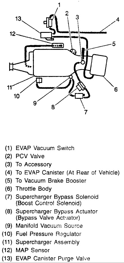
Are these both the same thing? If they are, do I have to remove the wire from PIN 30 and move it to PIN 66?
Looking at the alldata schematics for the L36 PCM, I am seeing on the Blue connector PIN 30-EVAP PURGE VALVE CONTROL. On my car, this valve is located on top of the charcoal canister behind the drivers side headlight.
For the L67, It is PIN 66 EVAP VACUUM SWITCH(VIN 1 ONLY), and according to this picture, it is located behind the supercharger.
Are these both the same thing? If they are, do I have to remove the wire from PIN 30 and move it to PIN 66?
Retired Senior Admin


Expert Gearhead
Joined: May 2006
Posts: 29,661
Likes: 43
From: Sheboygan Wisconsin
For the wires, look in electrical for a write up I did on adding a sense wire. That should answer that.
As for the heater hose, you can always swap the alt bracket with a different one.
As for the heater hose, you can always swap the alt bracket with a different one.
Thread Starter
Retired
Certified Car Nut
Joined: Jul 2003
Posts: 17,960
Likes: 1,839
From: Dark Side, AZ
Yup, already seen your post about the sense wire.
Will the L36 alt bracket work on this? I do have a spare one.
Senior Member
True Car Nut
Joined: Dec 2009
Posts: 9,616
Likes: 594
From: western,ny state
if i had hpt, i would be looking at getting rid of the evap and egr. you have a 97 so you still have to plug in to the dmv computer but i asked before and these guys said you can just make it not look for problems with those
Thread Starter
Retired
Certified Car Nut
Joined: Jul 2003
Posts: 17,960
Likes: 1,839
From: Dark Side, AZ
Dan, I just went out and did a test fit for the coolant/pulley assembly, and it does fit. The alternator does look like it would move position a little bit, but I won't know until I pull my working alternator off and do a test fit. Worst case scenario, I would have to change belt size....I just checked Rockauto. The accessory drive belt is the same for the 99 buick and my car. So, should be good!