
Heater Problem


Junior Member
Joined: Sep 2008
Posts: 7
Likes: 0
From: Grand Rapids, MI

If you have the auto temp control system with a digital readout, then you have a power feed to the blower control module that goes through fuse A3 in the Relay Center, a 30A. fuse.
It also has two other related fuses that go to the programmer which feeds the voltage to the lblower control module: Fuse 5A for 15 Amperes whic is labeled also as Aut A/C Cruise; and Fuse 9C which 10 Amperes and labeled MSC/RDO/CLSTR. The last one is keep alive, I believe.
There is no separate relay that powers the high speed setting with direct current from the battery instead of through a resistor pack as is on the basic HVAC unit.
Have you tested the blower motor itself? Always start with the simplest explanation. Law of Parsimony.
EDIT: I missed a fuse. There'* a fuse in the right side passenger fuse/relay block. It'* #11 and is 10 amperes. It'* the feedback fuse from the line to the blower motor that tells the programmer what voltage is b eing applied to the motor by the blower motor control module.
So far I have done the following.
Manually bypassed the blower fan with 12V and it works fine.
Checked all the fuses listed above. All are in good condition.
I pulled the blower control module out of the blower box. Now here is my question. How do I diagnosis if this part is bad, or if it is getting an incorrect signal?
Here is what I saw on the plugs that go into the blower control module (while unplugged) with the ignition ON and the blower / heat turned ON per the display screen:
Red Wire: 12V
Purple Wire: 1.86V
Black Wire: 0.05V
Grey with Black Stripe: 8.7V
Here is a pic showing the plugs I am referring to:
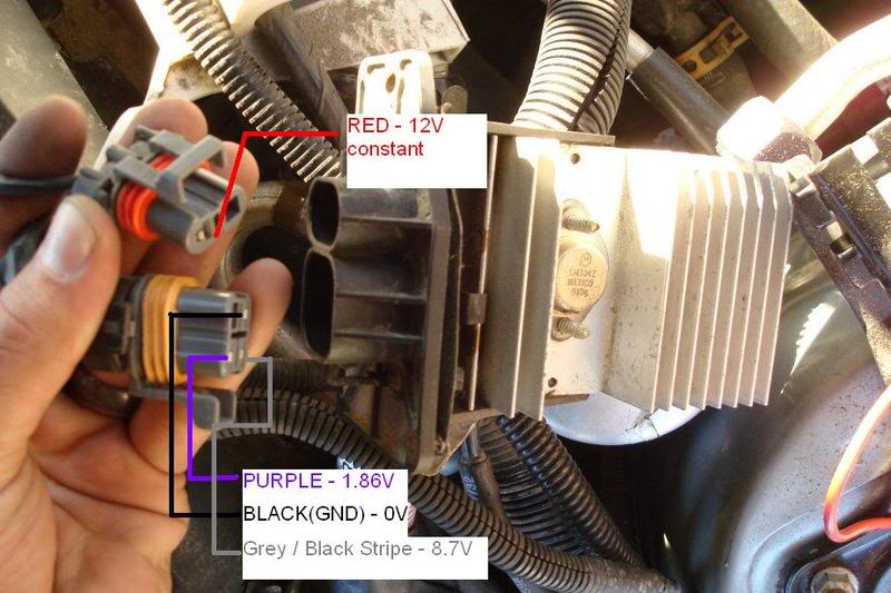
With the ignition and blower off, the Purple/Black & Grey with Black all go to 0V.
The reason I am confused is that when I turned the fan "up" to high, and then "down" to low, there was no change in the readings I saw at the plugs. I figured there would be some change in voltage, but perhaps it is a resistance circuit. I don't know. Can anybody help???
Thanks!!!

Thread
Thread Starter
Forum
Replies
Last Post

