Need to know how to wire an OBD1 data link connector
 01-15-2005, 04:43 PM
#1
Junior Member
Posts like a Ricer Type-R
Thread Starter

Join Date: Jan 2005
Location: Folsom California
Posts: 13
Likes: 0
Received 0 Likes
on
0 Posts

Think I have decided on an "Ease" GM OBD I Enhanced Powertrain Scan Tool. I want a PC based tool and this one looks pretty good. With an OBD I Cable its $315. The same unit comes with the OBDII cable for $350.
Of course, my '95 came with the 16 pin OBDII data link connector which is described in my shop manual but I see no reason why I could not save that 35 bucks and go with the OBD1 12 pin connector, since I have not yet installed either one.
This has been a longwinded way of asking... Does anyone have a shop manual that describes the 12 pin OBD1 connector so I would know how to wire it?
 01-15-2005, 05:52 PM
#2
Junior Member
Posts like a Ricer Type-R

Frankly, I'd go with the 16-wire OBD1/2 hybrid the 95 PCM and wiring harness came with to save headaches. Aside from that, anyone with a 92-93 FSM should be able to help. Alas, mine are still out on loan to DrJay up north.
01-15-2005, 06:28 PM
#3
Senior Member
True Car Nut

Join Date: Apr 2004
Location: Three Oaks, Michigan
Posts: 4,879
Likes: 0
Received 0 Likes
on
0 Posts
Are you asking to switch the OBDII Connector on the 94/95 Hybrid ECM, to the OBDI Connector that of the 93 and lower ECU'*? Not going to be easy, bud. If you are determined to switch connectors, why not make your own proprietary connector? Grab a 25 Pin D-Sub Connector [Also known as "Parallel/Printer port"], get the pin-out for the Scanner. All you would need to do, is check the resistance from one pin on the OBDII connector, and another on the end of the Scanner. When you get anything other than open, you've found where that connector goes, and you just keep doing that until you have the pin out. Then, just get to work on making it. Yeah, it would take a little time, and a soldering iron, but it would be the same to convert your OBDII Connector, to an OBDI. I am sure there is a member here with that scan tool, that wouldn't mind grabbing a pin-out for you.. so you wouldn't need to buy the cable. Or, just buy it, and return it once you are done with it.
-justin
-justin
01-15-2005, 06:51 PM
#4
Junior Member
Posts like a Ricer Type-R
Thread Starter
Join Date: Jan 2005
Location: Folsom California
Posts: 13
Likes: 0
Received 0 Likes
on
0 Posts
willwren,
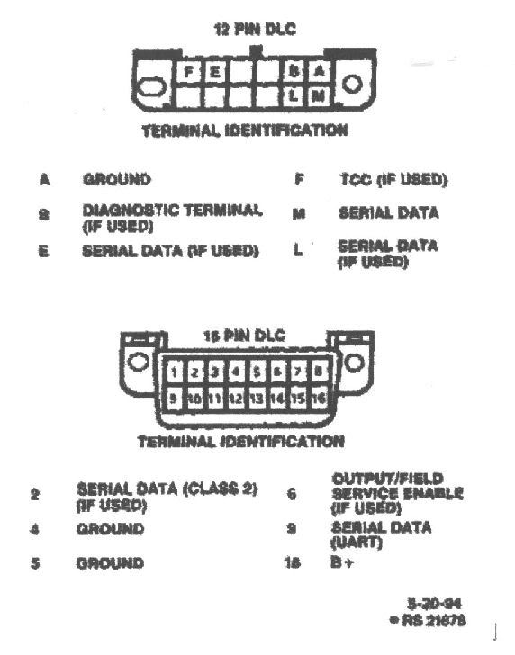
Thanks for the response but I can't see any real problems. The 16 pin OBDII connector actually has a max of only 8 wires, 2 of which are ground, one is B+, one is for HVAC which I would not use, 2 are for the CCR (Computer Command Ride controller), which I would not use. I have cobbled in some of the functions of the RAC system which is one of the connections (might use). So the only pin that is of real value to me, other than ground and B+ is '9', serial data. Every time I have looked into this I have scratched my head wonder'n why GM bothered to even use the OBDII (hybrid) connector.
So anyway, if someone out there has the wiring diagram for th 12 pin...
01-15-2005, 06:59 PM
#5
Junior Member
Posts like a Ricer Type-R
Thread Starter
Join Date: Jan 2005
Location: Folsom California
Posts: 13
Likes: 0
Received 0 Likes
on
0 Posts
Justin,
Thanks for the response. Basically thought about doing a version of what you said but I have found often times I have regreted modifying stuff for single purpose use. I actually have both connectors in my junk drawer. If I knew what pin on the OBD1 connector was ground, B+, and serial data, and maybe the RAC system that would be the easiest and most foolproof method of cobbling it in and using that scan tool unmodified.
Dave

 01-29-2005, 05:27 AM
#8
Junior Member
Posts like a Ricer Type-R
Thread Starter
Join Date: Jan 2005
Location: Folsom California
Posts: 13
Likes: 0
Received 0 Likes
on
0 Posts
Went ahead and ordered the "Ease" scan tool. $315. PC based. Ordered it with the OBD1 connector. As I suspected, it only needed 2 of the 12 pins connected. "A" - ground, and "M", serial data. This is my first experience with any scan tool and I really like it. Software install was straight forward, hookup was simple and worked the first time. Called tech support just to clear up a coupla questions. Great service, talked for about 1/2 hour, no bums rush.
I have had the engine running several times prior to getting the scan tool and one of the problems was a VERY high idle for a while, then it would settle down. Never knew what that was about till now. Tool showed a DTC 123 (TPS sensor high voltage).
Found that the reason for the high idle was I had hooked up the 'A' and "C" pins on the TSP backwards (+5V and Ground). But that is exactely what the manual indicated!
I have a main battery switch which I always turn off whenever I am done working on it. What I did not realize, is that I was reseting all DTC'* when I did that. Then, next session, main battery switch on, start it up, goes a little nuts with the high voltage reading and idles at 2500 till the DTC is set at which time it forces a more normal idle.
Anyway, I thought some members might like to 'see the Ease scan tool in use' so I captured several screens and other related photos depicting the process I went through to solve the problem and downloaded it all to a Yahoo album. Be sure and scroll down (if you have to) to read the 'name' and 'description' fileds as that is where I 'tell the story'.
I find it interesting that that error (in the shop manual) survived but then no one working on a stock Pontiac would have a reason to ever be aware of it.
Click on the link below...
http://pg.photos.yahoo.com/ph/bikeop...0a.jpg&.src=ph
02-04-2005, 12:54 AM
#9
Junior Member
Posts like a Ricer Type-R
Thread Starter
Join Date: Jan 2005
Location: Folsom California
Posts: 13
Likes: 0
Received 0 Likes
on
0 Posts
While getting this stuff figured out is critical to getting that old car on the road I am sure that the posts I make here fall into the category, for most of you, as 'Trivia'. Still, I think some of you may find it interesting so here goes...
After getting that TPS sensor problem solved. I moved on to a DTC that indicated the trans temp was -34 degrees. Remember, I am not using the PCM for the trans. Purchased an aftermarket TCU for that purpose, so that wire was hanging loose. But I want NO DTC'*, valid or not. Anyway, I found a chart in the manual that shows the temp. - ohms value relationship for that thermistor. Waltzed down to Radio Shack and purchased a 1/4 watt 330 ohms resistor, wired it in to pins BF14 and WC6 on the PCM... Bingo! Now the scan tool indicates the PCM thinks the (non-existent) 4T60E is running at a constant 174 degrees. No more DTC.
Next was a DTC for the Quad Driver Module #4. While I understand little about QDM'*, looks to me like they are some 'off the shelf' gizmo GM used to drive 4 different low amperage output devices such as a lamp or a relay. Anyway, #4 drives the MIL lamp, both engine cooling fan relays and the A/C request relay. I ran my single fan through the 'Fan 1 (low speed fan) circuit (works perfect) and I hooked up a red LED for the MIL lamp. The A/C request wire and the Fan2 wire were just hanging. After checking the resistance between pins 85 and 86(the coil) on a relay I had in my junk drawer, and finding it was about 90 ohms, made another trip to Radio Shack and picked up a few 1/4 watt 100 ohm resistors. Wired one into each unused wire, ran the other to Run B+ (most of the time the PCM switches to 'ground'), fired it up and Waa Laa, no more DTC.
I was surprised to find that the PCM generates a DTC for an unconnected wire, even if no request is being made of the component that is supposed to be there, but is not.
So, anyway, as I write, the thing is DTC free.
Thanks for all the input and interest, and suggestions on this thread.

Thread
Thread Starter
Forum
Replies
Last Post