1963 Pontiac Catalina massive project build thread
 05-07-2014, 03:35 PM
#291
Senior Member
True Car Nut


without that box it will be very hard to do what you are wanting to do. all you are going to have is the mechanical advance on the dist. and then you will have to mess with it every time you want to change from street mode to strip.
i have a mallory 85 all in one hei. i have a pretty good size cam and have to run about 18-20degrees at idle and it ends up at 36degrees. if you know of a way to make this type go backward without some sort of retard box i would be curious to learn about it.
i have a mallory 85 all in one hei. i have a pretty good size cam and have to run about 18-20degrees at idle and it ends up at 36degrees. if you know of a way to make this type go backward without some sort of retard box i would be curious to learn about it.
 05-07-2014, 03:55 PM
#292
Senior Member
Posts like a Turbo
Thread Starter
You are right Justin. The centrifugal advance can not be stopped or retarded mechanically. You can only lock it out. BUT! I've been playing in my head with using the vacuum advance canister to retard it IF it will push it into retard with the boost??? Meaning, if the canister will move the bottom plate in advance, maybe, if with the boost, it can push the canister the opposite direction, it can retard the bottom plate??? I do have a full Accel 300+ (plus) and the additional 375 ignition system with electronic boost retard to help. But t would be great to have a mechanical way to retard the timing. Of course the engine going to boost will at least let the vacuum canister return to it'* base position (zero vacuum) even if boost does not move it farther. So in effect it is a boost retard.
Wait a minute. I think I'm getting a little retarded trying to think of all this. LOL.
Mark
Wait a minute. I think I'm getting a little retarded trying to think of all this. LOL.
Mark
05-08-2014, 03:35 AM
#294
Senior Member


True Car Nut
Mark Im not sure if this information is helpful but could u not use a variable vacuum advance, to limit timing ...after you have the curve set..
__________________
1997 Buick Pk Ave (Soft Ride) Suspension!
1997 Buick Pk Ave (Soft Ride) Suspension!
05-08-2014, 10:20 AM
#295
Senior Member
Posts like a Turbo
Thread Starter
Art, not sure I know what you mean by a variable vacuum advance??? Unless you mean the adjustable limiting vacuum canister usually sold by Crane etc. If you are, they only limit the travel within the canister so you can set the total mechanical plus vacuum advance range. I don't see how they would help or hinder a retard system. Unless they would actually "retract" during boost?? But let me know if you are thinking of something different.
Mark
Mark
06-06-2014, 10:30 PM
#296
Senior Member
Posts like a Turbo
Thread Starter
Art you asked about making a mechanical advance system work with boost. I have a solution, not sure it is optimal but I think it can work.
You set the initial, mechanical and vacuum advance to match the needs of the engine N/A (off boost). The vacuum of course will retract (retard) as soon as you lose vacuum and definitely once the boos starts. The mechanical will still do its thing ramping up with the centrifugal force as the motor rpms up. That'* when you program in the electonic boost retard to pull back the timing to counteract the mechanical advance and bring the total all back to 26ish degrees.
The vacuum is out of it so lets just talk about the mechanical and the boost retard. Lets say you are running an initial of 12 degrees. Then lets say you use the mechanical to bring it up to 32 degrees so the engine runs its best N/A. If you have the initial and mechanical all in by 2600 rpm you are going to want it back to about 22 on boost. Use the boost retard to pull back the timing to compensate. If you are running a total of 10 psi then while the motor mechanically is hitting 32 by 2600 rpm, the boost can be set for 1 degree for each pound a that will electronically pull it back to 22 at 10 psi. A good boost retard should allow incremental settings, such as 1.5 or 2.5 degrees per pound so you can pull it back exactly how much you want depending on how much boost you run. Let me know if you think that can work. You must make sure the electronics are working or you'll be sending your heads to the Moon, LOL. If it stops working.
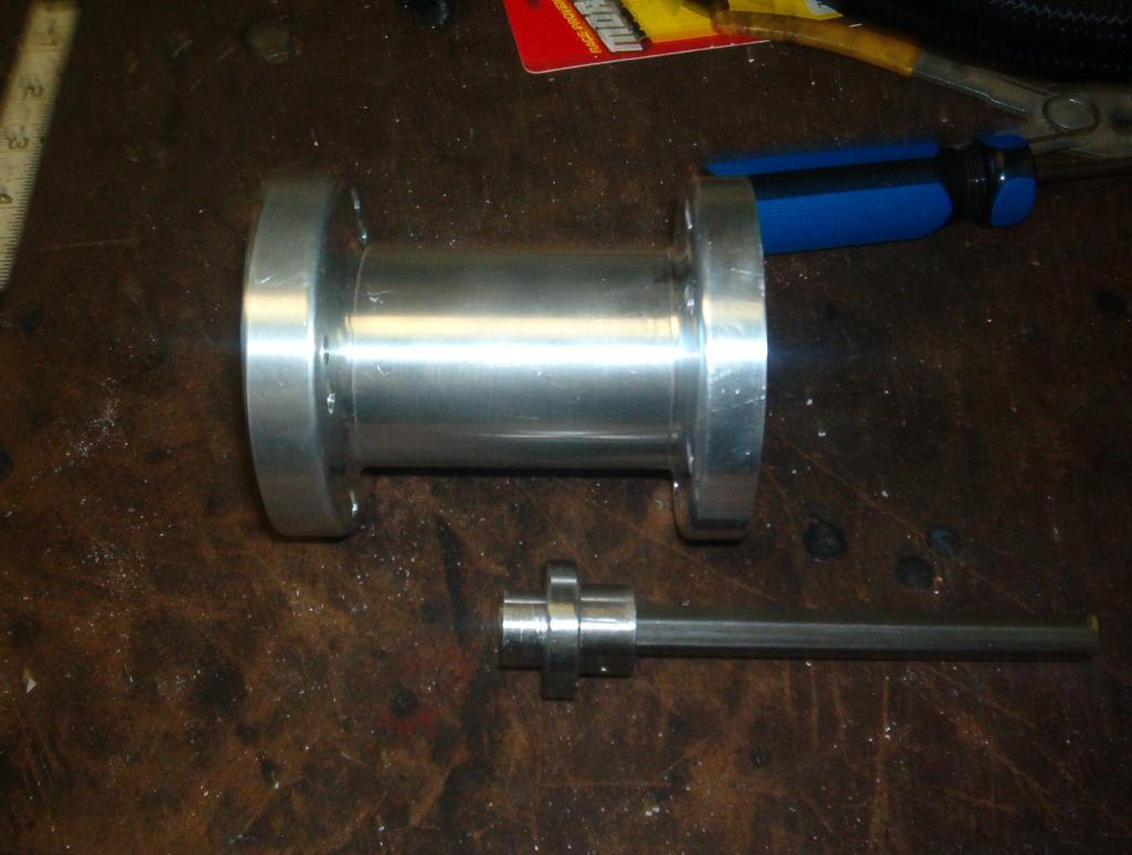
I've been staying out of the garage because of 110 degree temps. But I've been doing my homework on making a front drive distributor. I took into consideration the thought you guys had about the shaft running in the sintered bearings on its side. SOOO!! I purchased a new Pro-Comp electronic billet distributor with the top roller bearing. I've blown apart the distributor already but I took a pic of the principle parts.

In it you can see the distributor, distributor shaft, the pump extension and the extension roller bearing and the hex drive shaft in the bearing.
This is the extension again. The top end of the pump extension pic shows the shoulder that is machined into the inside of the extension to seat the bearing.

The bearing normally installs into the top of the extension so it sits almost flush with the opening. Then the hex drive goes through the bearing and the pump would sit down into the slight relief (pocket) at the flange and the pump shaft would fit into the hex drive end. What I'm going to do is bring the bearing in from the opposite end of the extension and locate it about half way down the inside of the extension. Cut off the distributor housing shaft and have it machined down in steps so it fits in snug to the top of the extension. The first cut from the top of the distributor will match the first opening diameter of the extension, the second cut will match the reduced "step'" that originally stopped the bearing (the bearing shoulder). The following pics kind of lays out where everything will line up.

I think I found a machinist to work with. So I'll be taking it there soon.
With this set up the top of the distributor shaft will be riding in a roller bearing, the mid point of the shaft, where it will get machined to fit the hex shaft adaptor, will ride in a roller bearing, and the end be inserted into the pump drive hex receiver mounted on the cam. The last thing will be to cut the distributor shaft to length and have the end cut to a hex to fit the hex drive adaptor end.
The distributor I bought is a Chevy with a slip collar to locate it where I need it to be so that will allow some latitude in how long I make the housing shaft. I think it will work out fine. More pics coming as I get the machining done.
Mark
You set the initial, mechanical and vacuum advance to match the needs of the engine N/A (off boost). The vacuum of course will retract (retard) as soon as you lose vacuum and definitely once the boos starts. The mechanical will still do its thing ramping up with the centrifugal force as the motor rpms up. That'* when you program in the electonic boost retard to pull back the timing to counteract the mechanical advance and bring the total all back to 26ish degrees.
The vacuum is out of it so lets just talk about the mechanical and the boost retard. Lets say you are running an initial of 12 degrees. Then lets say you use the mechanical to bring it up to 32 degrees so the engine runs its best N/A. If you have the initial and mechanical all in by 2600 rpm you are going to want it back to about 22 on boost. Use the boost retard to pull back the timing to compensate. If you are running a total of 10 psi then while the motor mechanically is hitting 32 by 2600 rpm, the boost can be set for 1 degree for each pound a that will electronically pull it back to 22 at 10 psi. A good boost retard should allow incremental settings, such as 1.5 or 2.5 degrees per pound so you can pull it back exactly how much you want depending on how much boost you run. Let me know if you think that can work. You must make sure the electronics are working or you'll be sending your heads to the Moon, LOL. If it stops working.
I've been staying out of the garage because of 110 degree temps. But I've been doing my homework on making a front drive distributor. I took into consideration the thought you guys had about the shaft running in the sintered bearings on its side. SOOO!! I purchased a new Pro-Comp electronic billet distributor with the top roller bearing. I've blown apart the distributor already but I took a pic of the principle parts.
In it you can see the distributor, distributor shaft, the pump extension and the extension roller bearing and the hex drive shaft in the bearing.
This is the extension again. The top end of the pump extension pic shows the shoulder that is machined into the inside of the extension to seat the bearing.
The bearing normally installs into the top of the extension so it sits almost flush with the opening. Then the hex drive goes through the bearing and the pump would sit down into the slight relief (pocket) at the flange and the pump shaft would fit into the hex drive end. What I'm going to do is bring the bearing in from the opposite end of the extension and locate it about half way down the inside of the extension. Cut off the distributor housing shaft and have it machined down in steps so it fits in snug to the top of the extension. The first cut from the top of the distributor will match the first opening diameter of the extension, the second cut will match the reduced "step'" that originally stopped the bearing (the bearing shoulder). The following pics kind of lays out where everything will line up.
I think I found a machinist to work with. So I'll be taking it there soon.
With this set up the top of the distributor shaft will be riding in a roller bearing, the mid point of the shaft, where it will get machined to fit the hex shaft adaptor, will ride in a roller bearing, and the end be inserted into the pump drive hex receiver mounted on the cam. The last thing will be to cut the distributor shaft to length and have the end cut to a hex to fit the hex drive adaptor end.
The distributor I bought is a Chevy with a slip collar to locate it where I need it to be so that will allow some latitude in how long I make the housing shaft. I think it will work out fine. More pics coming as I get the machining done.
Mark
Last edited by Marks02bonneville; 06-06-2014 at 10:32 PM.
06-07-2014, 12:02 AM
#297
Senior Member
True Car Nut
Very interesting to say the least Mark. It is very easy to confuse me on this build! How does this all work?
Can you how explain how you program in the electonic boost retard to pull back the timing and make it precise & reliable?
Can you how explain how you program in the electonic boost retard to pull back the timing and make it precise & reliable?
__________________
1997 Buick Pk Ave (Soft Ride) Suspension!
1997 Buick Pk Ave (Soft Ride) Suspension!
Last edited by Soft Ride; 06-07-2014 at 12:04 AM.
06-07-2014, 01:41 AM
#298
Senior Member
Posts like a Turbo
Thread Starter
The boost retard is easy. The system just takes the setting you choose, 1 degree retard per pound of boost (or .5 pound, or 1.2 pound, depending on how much it allows you to retard per pound). When the box/controller starts to sense boost it starts to retard the ignition spark the set amount of boost per pound. The only scary part is if the electronics fails. So when you are relying on an electronic boost retard controller, you just need to do everything in your power to make sure there is a solid wiring and power supply. If the controller itself fails there is not much you can do to prevent that. Most systems use a GM MAP (manifold air pressure) sensor to read the boost pressure. Then does its thing off of that.
Mark
Mark
The following users liked this post:
Soft Ride (06-07-2014)