1963 Pontiac Catalina massive project build thread
 12-14-2012, 08:45 PM
#111
Senior Member
Posts like a Turbo
Thread Starter
Well, got a call from Paul down in Tuscon saying my motor should be Friday (today). Told him it will be Monday before I can get it. He had to finish assembling the heads and put them on. A little later I get an e-mail from him again. He started putting in the rocker studs and the first one he tried to torque down stripped out the threads. Now he has to drill and tap and Heli-Coil all of the stud holes for insurance. So many things with the heads that I did not expect. Damn.
HEY!!! Knock on the door. UPS Man, Santas Helper. LOL. I just had twins---LOL.
Like Scareface said in that movie----"LET ME INTRODUCE YOU TO MY LITTLE FRIENDS"--HEH. I'm back to happy again.
Twin 750 Blow Thru E-85 power mongers.
Markus O'Powerous!!!!!
HEY!!! Knock on the door. UPS Man, Santas Helper. LOL. I just had twins---LOL.
Like Scareface said in that movie----"LET ME INTRODUCE YOU TO MY LITTLE FRIENDS"--HEH. I'm back to happy again.
Twin 750 Blow Thru E-85 power mongers.
Markus O'Powerous!!!!!
 12-16-2012, 10:21 AM
#112
Senior Member
Posts like a Turbo
Thread Starter
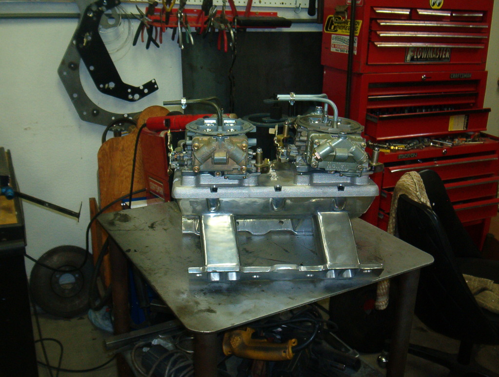
I was asked about the carb hat and it'* orientation so they could make and position the tubes into the air stream. You see them the way they are because the cabs will be sideways mounted using the Shotgun scoop. So I had to tell them which way the carbs will mount. I determined that they will mount with the throttle linkage on both carbs facing the front, hence the tubes facing towards the linkage. I cut out a 1/4th inch aluminum plate to make the bottom plate of the scoop. I found some 1 inch aluminum spacers to mount that plate on over the carbs and they will get welded on once I determine the exact location the scoop will sit.
This is the carbs with the aluminum spacers.
This is the plate I made just sitting in the bottom of the scoop.
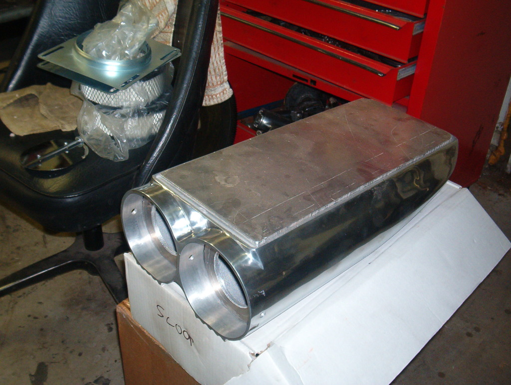
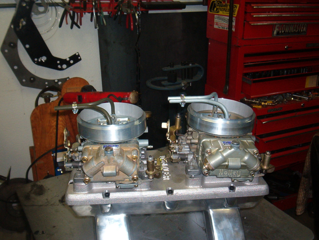
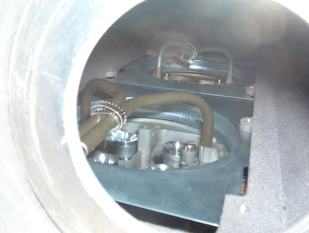
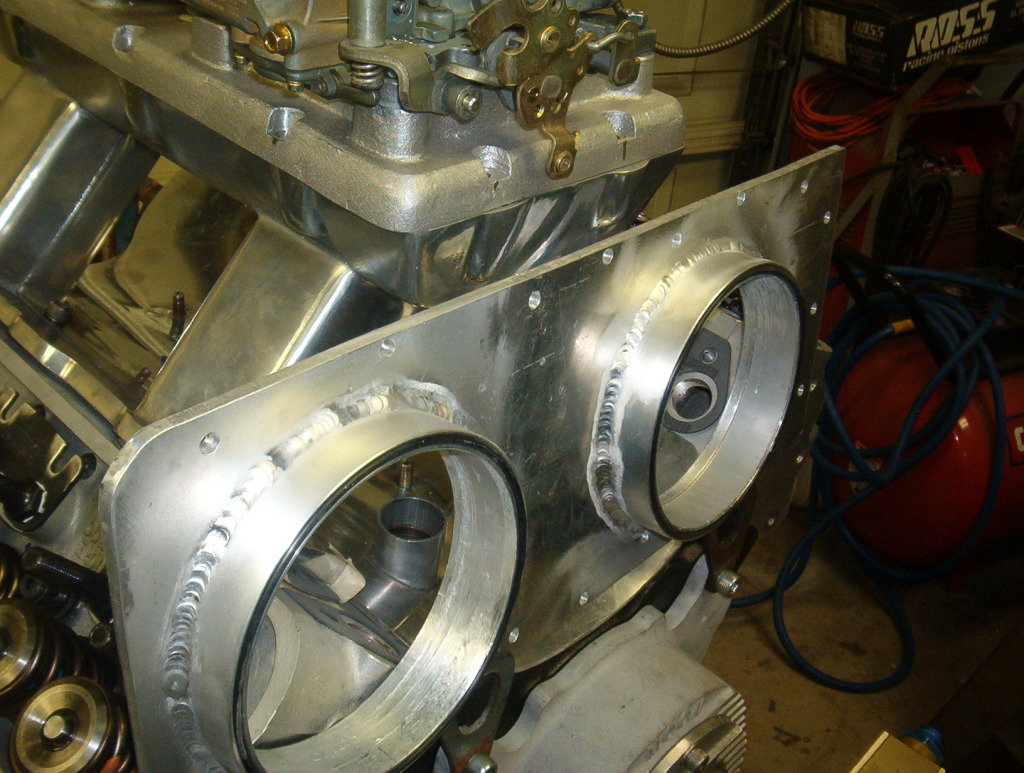
This is a look inside of the scoop sitting on the carbs with the tubes facing forward.
And the scoop on top of the carbs. Since I do not have the holes located and cut in the 1/4 inch plate yet I used the original stamped sheet carb spacers under the scoop just for mock up. You can see the new spacers laying on the plate in front of the assembly.
I have to talk to Dennis at CSU to see if I can shorten the tubes since the front carb tubes are close to the inside front of the scoop itself. Which could cause a different pressure affect seen by the front carb versus the rear carb.
Mark L
This is the carbs with the aluminum spacers.
This is the plate I made just sitting in the bottom of the scoop.
This is a look inside of the scoop sitting on the carbs with the tubes facing forward.
And the scoop on top of the carbs. Since I do not have the holes located and cut in the 1/4 inch plate yet I used the original stamped sheet carb spacers under the scoop just for mock up. You can see the new spacers laying on the plate in front of the assembly.
I have to talk to Dennis at CSU to see if I can shorten the tubes since the front carb tubes are close to the inside front of the scoop itself. Which could cause a different pressure affect seen by the front carb versus the rear carb.
Mark L
12-31-2012, 01:20 AM
#113
Senior Member
Posts like a Turbo
Thread Starter
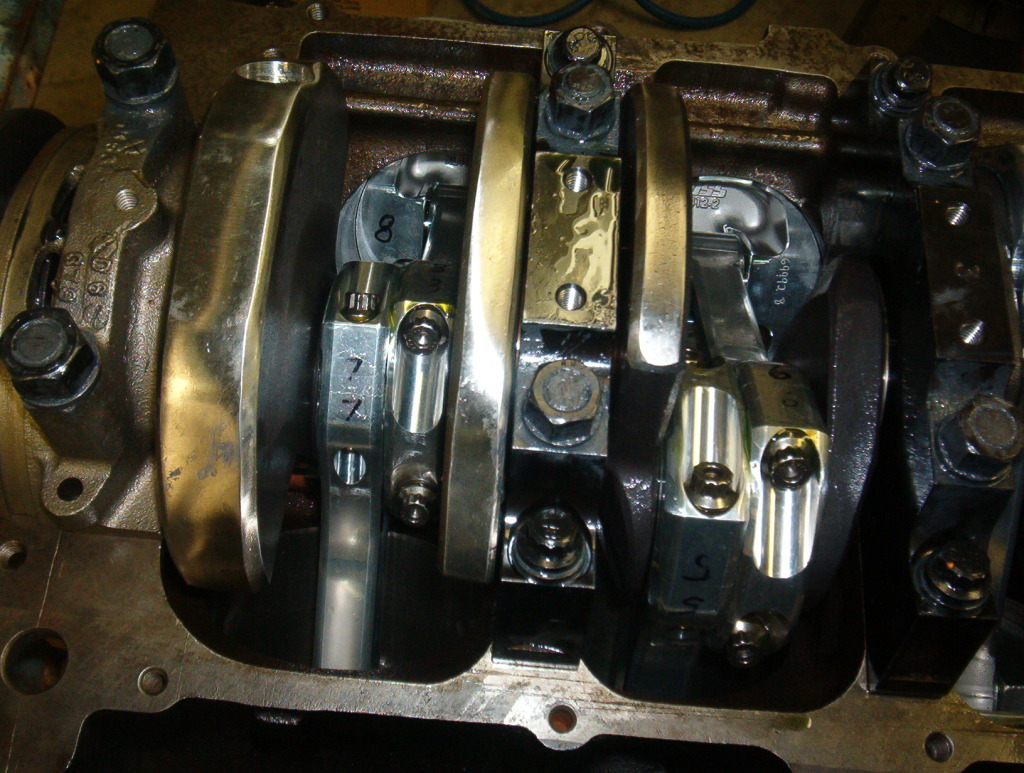
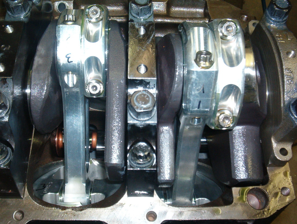
This a couple of pics of the motor. This is a close up of the rear half of the lower end. You can see the aluminum rods, and the splayed 4 bolt mains. The polished look of the bottom of the counterweights is the result of having a really light rotating assembly. They had to remove a lot of the counterweight material just to get it all balanced. So it has a very good balance job. If you look up just above the pistons, at the block area between the mains, you can see the reinforcing rib that Pontiac cast into its early blocks. That, thicker main webs, thicker cast walls etc., and more nickel in the iron makes the early blocks much stronger and more wear resistant than later thinner cast blocks. This same basic block is in my friends 3000 HP nostalgic nitro burning fueler. So it ought to hold up to my little 1500 HP.
The front half of the bottom end.
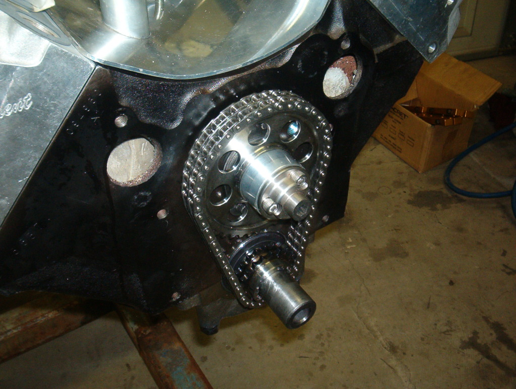
A shot of the timing chain and the drive spud for the cam drive front Hilborn fuel pump.
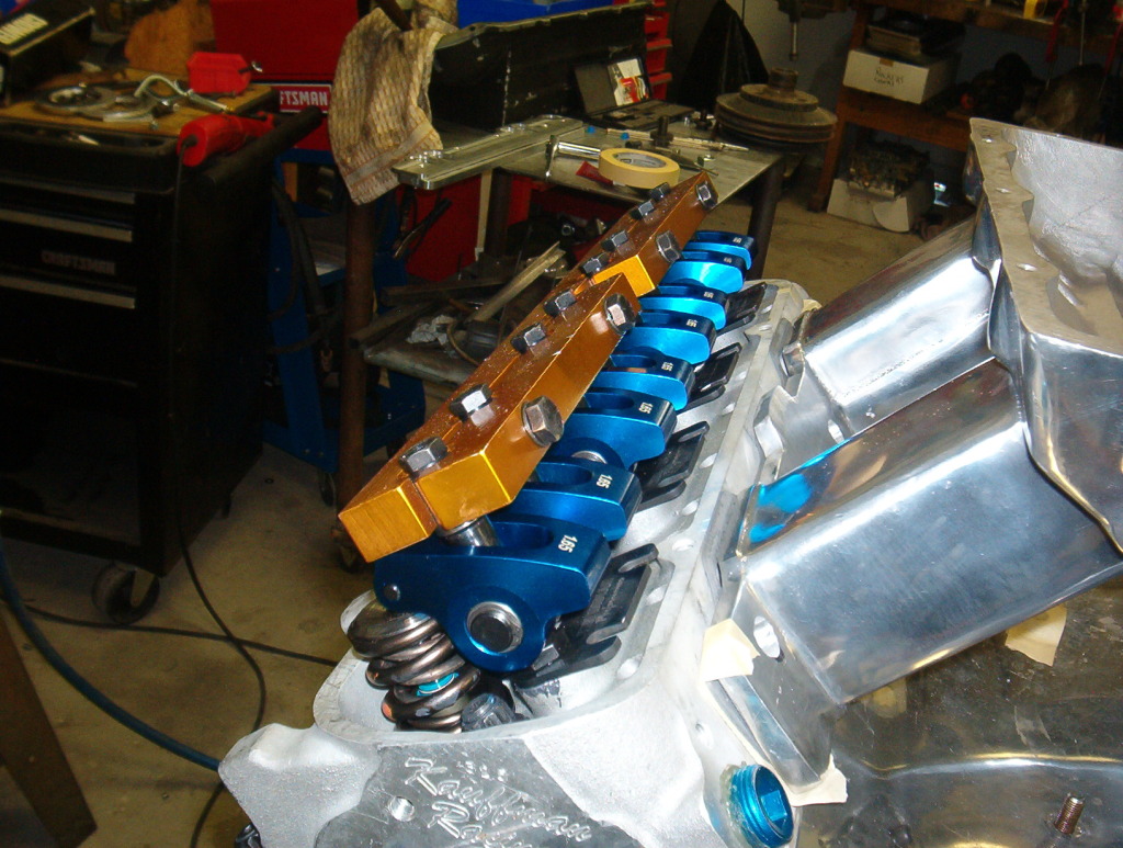
A pic of the Scorpion 1.65 aluminum rockers and the stud girdle. No push rods installed, just mocked up to look for anything that could be wrong.
More coming.
Mark L
The front half of the bottom end.
A shot of the timing chain and the drive spud for the cam drive front Hilborn fuel pump.
A pic of the Scorpion 1.65 aluminum rockers and the stud girdle. No push rods installed, just mocked up to look for anything that could be wrong.
More coming.
Mark L
12-31-2012, 01:37 AM
#114
Senior Member
Posts like a Turbo
Thread Starter
I finally got the motor home. After placing the T ram on the actual motor I found that the head flanges had been cut sometime in its history. One side some but flat, the other a lot and crocked. I've been busy trying to get the manifold to fit well enough to work as it is by making aplate spacer and using the gaskets to get the right manifold height. The manifold flanges were cut not only to much making the manifold set too low in the valley between the heads, but one side was even cut on an angle, probably why no one ever ran it. Lucky me, I was next in line. When I cut the spacer off of the thick flange I used a piece of angle iron clamped to the little my saw plate on my band saw. I set it up on an angle in relation to the blade and I was able to get the spacer cut on an angle, thicker on one side than the other. Just like making a wood shim. The flange that was cut straight is the passenger side, and that side gets two gaskets and that is all. The angle cut side got two gaskets and the spacer. Luckily, the ports on the manifold were still a little undersized compared to my larger head ports so by getting the manifold all lined up with everything, I was able to finish port the manifold port outlets and it is almost a perfect fit. I just glued the single set of gaskets to the head aligned wth the head ports, and I glued the second set of gaskets to the manifold. This will allow me to drop the manifold down into place with the good side bolted down just about finger tight and aligned. The spacer will be laying on the other head over the ports and with the manifold aligned on the good side, I can position the spacer on the bad side looking thru the manifold down the ports and bolt it all together.
Gaskets and spacer in place.
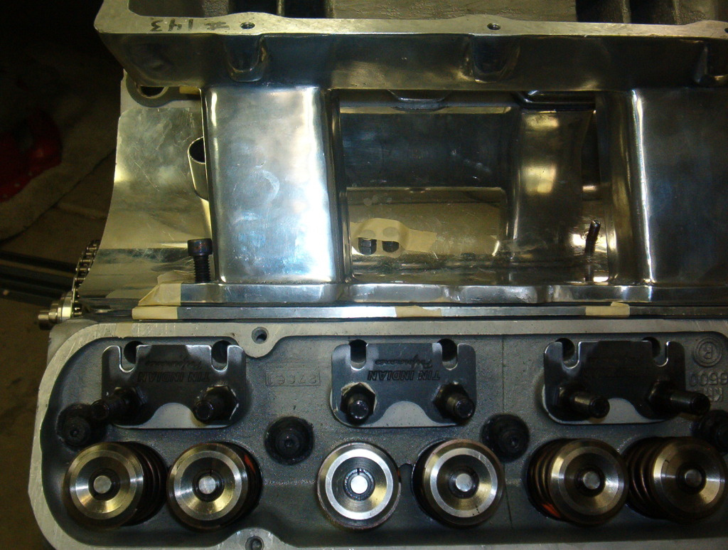
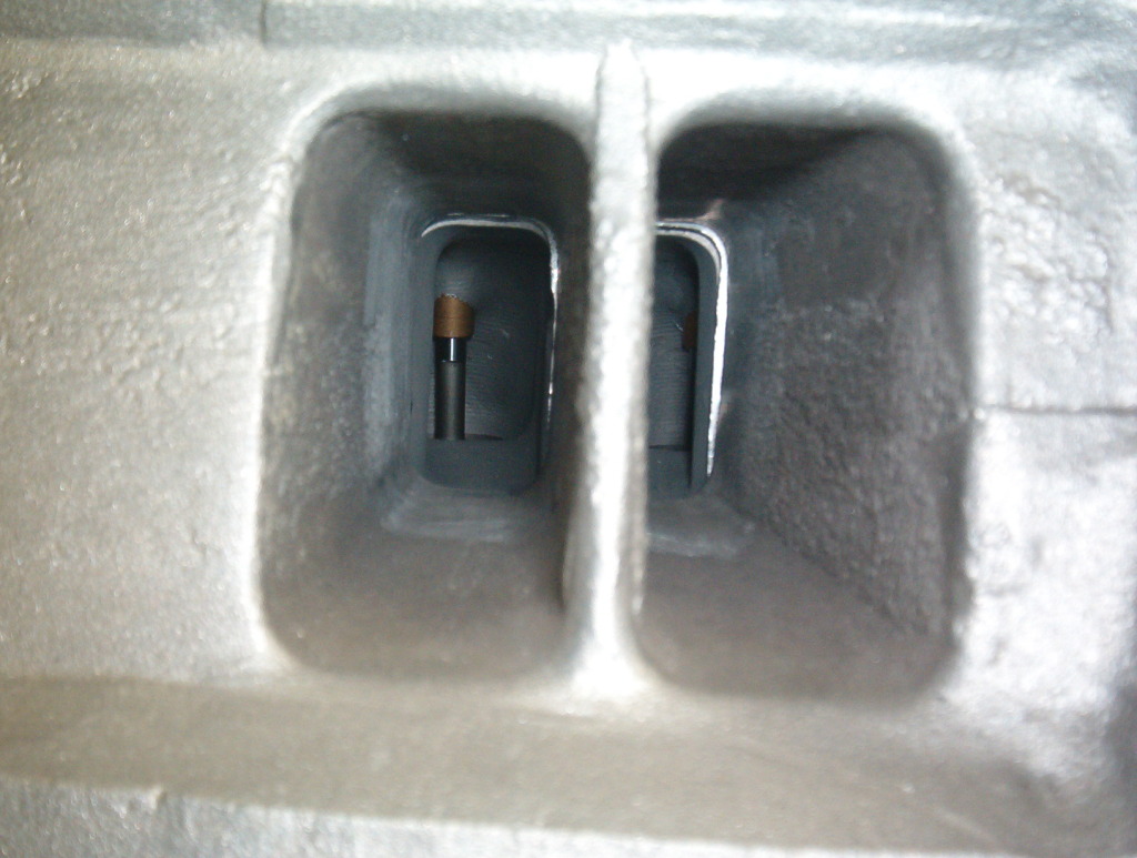
Looking down the good side ports all aligned.
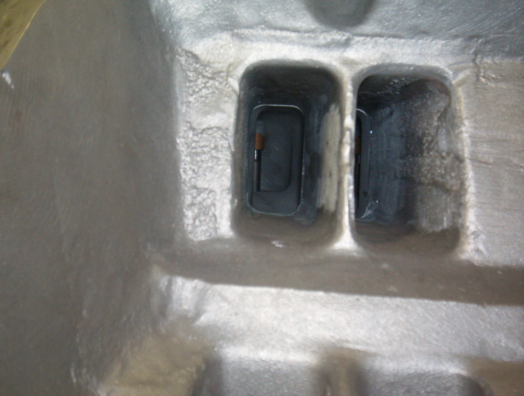
This is looking down the bad side ports with the spacer just peaking out (the shiny edges you can see). By moving the spacer around then bolting it all down I should be able to get everything almost perfect in the bad ports as well. There will be a little bit of rough transition as the air/fuel passes the gaskets and spacer but there won't be any blunt edges to hit on.
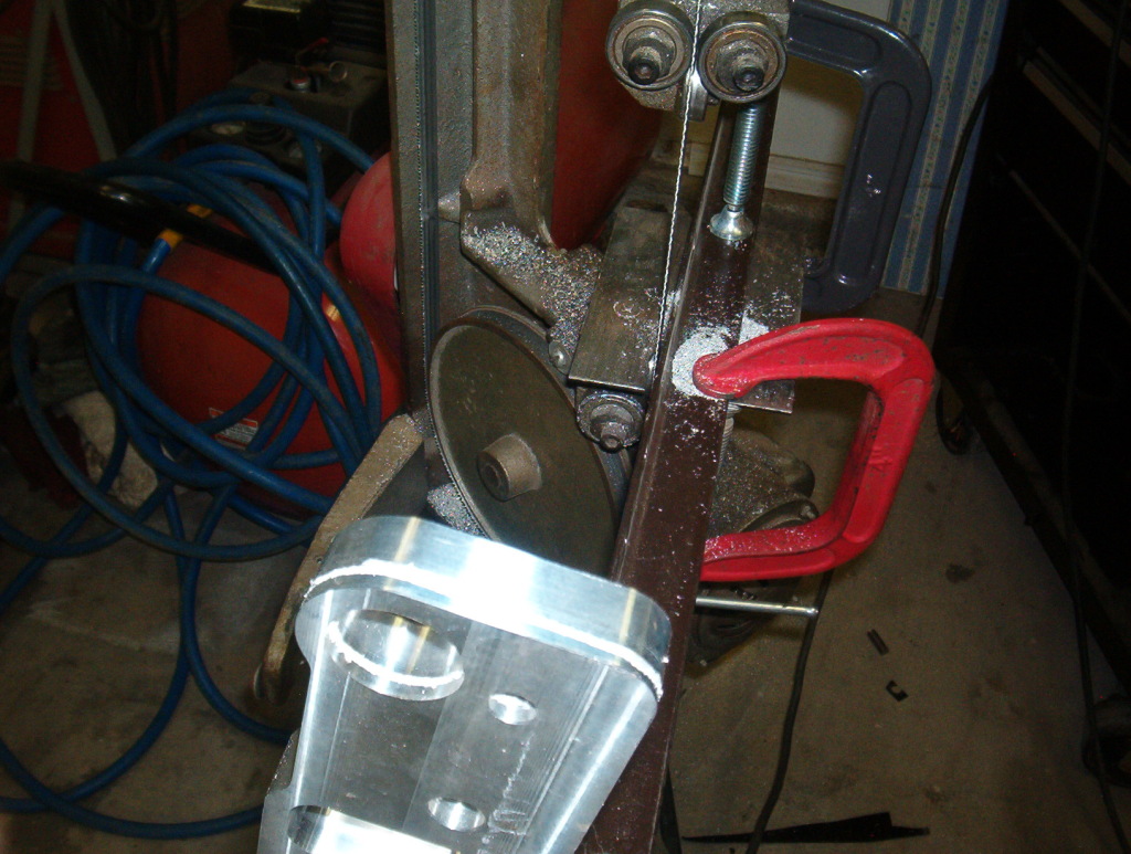
This how I set up the saw. Angle iron back fence set at an angle. After I made that starting cut that you see in the pic, and after the pic was taken, I added another angle piece in front of the flange to hold it tight at the saw blade so it could not wander. Believe it or not, it all worked---damnnnnn, HA!
More pics coming of the motor.
Mark L
Gaskets and spacer in place.
Looking down the good side ports all aligned.
This is looking down the bad side ports with the spacer just peaking out (the shiny edges you can see). By moving the spacer around then bolting it all down I should be able to get everything almost perfect in the bad ports as well. There will be a little bit of rough transition as the air/fuel passes the gaskets and spacer but there won't be any blunt edges to hit on.
This how I set up the saw. Angle iron back fence set at an angle. After I made that starting cut that you see in the pic, and after the pic was taken, I added another angle piece in front of the flange to hold it tight at the saw blade so it could not wander. Believe it or not, it all worked---damnnnnn, HA!
More pics coming of the motor.
Mark L
12-31-2012, 11:54 AM
#115
Senior Member
Posts like a Turbo
Thread Starter
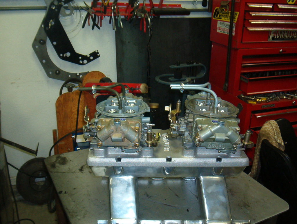
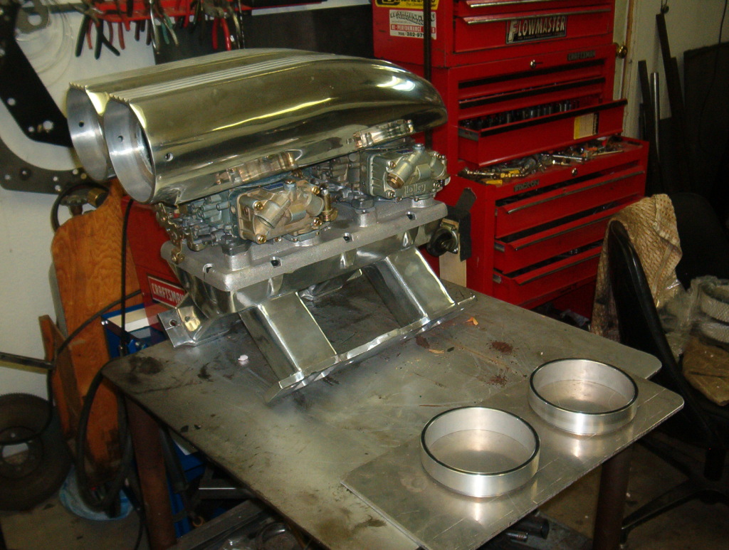
I took pics of the motor with all three of the different kinds of valve covers that I have at my disposal. Give me your thoughts on which ones you think look th ebest to use. The Cal Custon ribbed aluminums. These are old school items that I got on the '59 motor, so they are original '60 valve covers made back then.
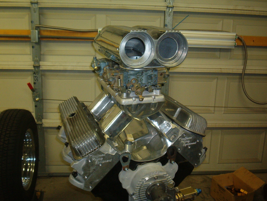
These are a pair of '64 GTO covers that have the tall oil breather tubes. These would work well adding tubes from those long oil breather extensions up to a catch can on the firewall to catch the oil vapors.
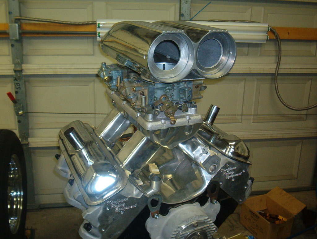
These are a set of fabricated newer style covers that I got from my son for my Birthday.
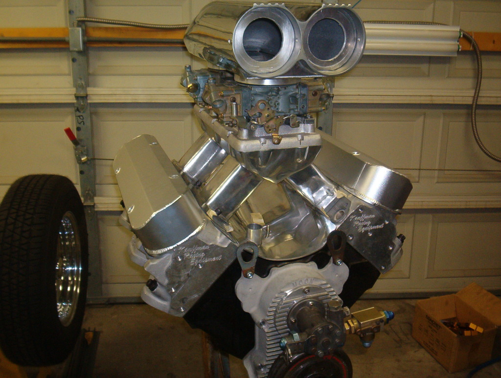
Which ones do you think look the best for my motor? Mark L
These are a pair of '64 GTO covers that have the tall oil breather tubes. These would work well adding tubes from those long oil breather extensions up to a catch can on the firewall to catch the oil vapors.
These are a set of fabricated newer style covers that I got from my son for my Birthday.
Which ones do you think look the best for my motor? Mark L
12-31-2012, 12:13 PM
#116
Senior Member
True Car Nut
Join Date: Sep 2006
Location: Indianapolis, IN
Posts: 4,606
Likes: 0
Received 0 Likes
on
0 Posts

Great work! You have nice and detailed posts. I love the progress! I think you should use the new fabbed covers, and it'* because I've seen those types of covers on other insanely powerful engines. No pressure.
12-31-2012, 02:44 PM
#117
Senior Member
Posts like a Turbo
Thread Starter
Thanks for the nice comments. I've watched and read posts for so many years that are so vague that it does not help anything. I just try to be a little more explanative to help make things less ambiguos. But. No pressure, yeah right, lol. The fab'd covers would bolt right on and I would not need spacers, the other two both require spacers. But the GTO covers have the nice breather tubes that I could add tubing to and run up to a breather/vapor accumulator on the firewall. Either of the other two covers will require some kind of fabrication for that. It'* 6 of this and half a dozen of the other. I think it'll come down to personal taste. I wished the motor had three heads, then I could run one of each. Jezz, did I just say that??? LOL. If I knew what I could get for each set on resale (online etc) it could come down to how which is the cheaper set to keep and get some money back off the others?? Not sure that'* true Hot Rodding but it is my Hot Rodding. MArk L
12-31-2012, 09:50 PM
#119
Senior Member
Posts like a Turbo

Join Date: Aug 2010
Location: Green River wy
Posts: 256
Likes: 0
Received 0 Likes
on
0 Posts
I like the look of the fab covers , but really would go with the old style ribbed and can see how you like to do a lot of your own fabbing.
01-01-2013, 02:15 AM
#120
Senior Member
Posts like a Turbo
Thread Starter
Thanks for the input guys. I post on several forums and I've had many different opinions but one was interesting, and something I had not even thought of. The scoop is ribbed on the top, similar to the ribbed valve covers. The thought was to use the ribbed covers to match the scoop. After I paint the motor I plan to paint the scoop between the ribs. If I paint the between the ribs on the valve covers it would make a nice match. That might just seal the deal.
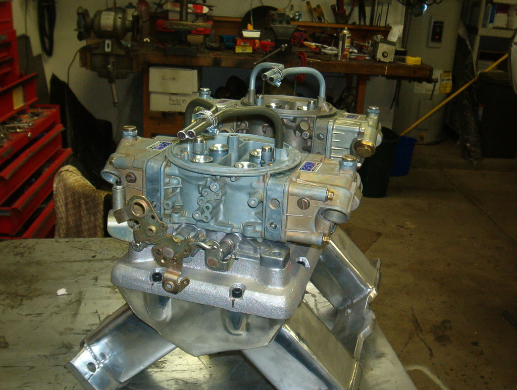
This is the plate I made to mount the Shotgun blower scoop to my carburators. I drilled and tapped it to match the little bolt pattern on the bottom of the scoop. Then I added more bolt locations between the originals to better seal up the scoop to the plate. I found two aluminum carb hat spacers online that are used to raise the turbo carb hats. They come with an O-Ring on the bottom of the spacers to seal them to the carbs. Once I located them to the plate using the assembled carbs and t ram top, I took it all to the welder and had him finish weld them to the plate. This is the finished plate on the carbs.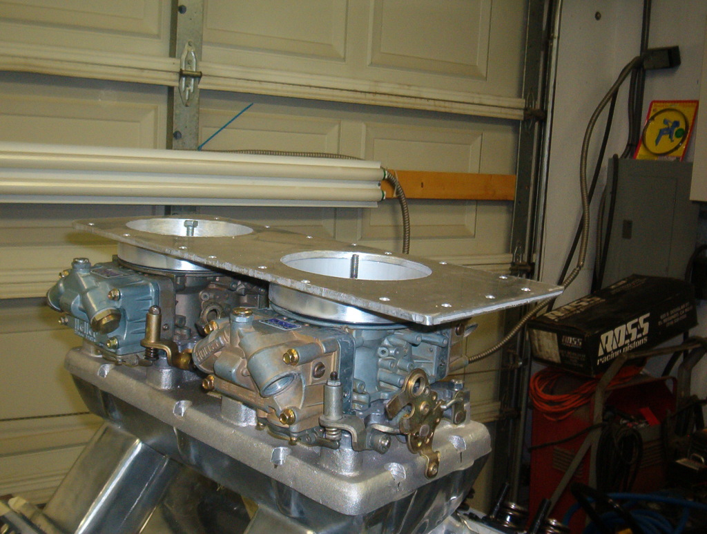
A pic of it laying on the motor so you can see the spacers welded to the plate.
The pics in the previous post about the valve covers shows the final assembly of the carbs on the manifold , the carb plate, and the blower scoop laying inplace on top of that the plate.
Mark L