ICM test
 06-08-2011, 07:59 PM
#1
Retired Senior Admin


Expert Gearhead
Thread Starter
Join Date: May 2006
Location: Sheboygan Wisconsin
Posts: 29,661
Likes: 0
Received 28 Likes
on
24 Posts


Testing the Ignition Control Module (ICM)
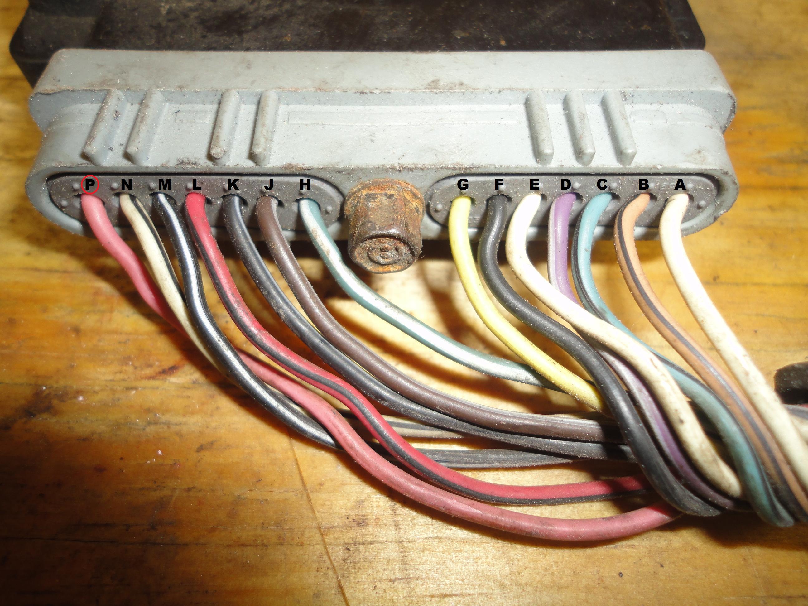
 Each circuit is described by a letter. If you look closely at the connector (on the car) you'll find these exact same letters cast on it.
Note- Some of the colors of the wires may not necessarily be the colors on the vehicle you're working on. Don't worry, because the circuit descriptions don't change. You will still be able to successfully diagnose the NO START Condition with this information.
Also, you’re specific vehicle may not have all of the wires coming out of the Ignition Control Module (ICM), this is also no cause for concern. since it will be exact same Ignition Module as long as this is a 3.8l.
Checking for Power (12 V)
 First, make sure the ICM is receiving 12 volts. Not a lot of room to work here, I recommend using a wire piercing probe to do all of these tests.
  . Whatever you use, the key here is to be careful.
 Now we will check that the ICM has a good GROUND. The Ground wire is the K circuit.
Testing the 3X-18X CKP Sensor'* Power Circuit
 Now lets test that the ICM is providing 12 Volts to the CAM and CRANK Position Sensors. They are both fed threw the same wire coming out of the ICM. This is the N wire.
 Now test the CRANK (18X CKP) Signal from Crankshaft Position Sensor. This is the G wire.
Verifying the 3X CKP Sensor Signal
 Now test the 3x sync signal This is the H wire.
Note- Some of the colors of the wires may not necessarily be the colors on the vehicle you're working on. Don't worry, because the circuit descriptions don't change. You will still be able to successfully diagnose the NO START Condition with this information.
Also, you’re specific vehicle may not have all of the wires coming out of the Ignition Control Module (ICM), this is also no cause for concern. since it will be exact same Ignition Module as long as this is a 3.8l.
- A- WHITE wire.
- ECM control of Ignition Control Module (after the 400 RPMs and above are achieved).
- B- TAN with BLACK stripe wire.
- 5 Volt BYPASS from ECM for Ignition Timing Control.
- C- LIGHT BLUE with BLACK stripe wire.
- CRANK Position Signal to ECM.
- D- PURPLE with WHITE stripe wire.
- Fuel Injection Control Signal to ECM.
- E- WHITE wire.
- Instrument Panel Tachometer Signal.
- F- BLACK wire.
- CAM Signal from the Camshaft Position (CMP) Sensor.
- G- YELLOW wire.
- CRANK (18X CKP) Signal from Crankshaft Position Sensor Assembly.
- H- LIGHT BLUE with WHITE wire.
- SYNC (3X CKP) Signal from Crankshaft Position Sensor Assembly.
- J- BROWN with WHITE stripe wire.
- CAM Signal from Camshaft Position (CMP) Sensor.
- K- BLACK with WHITE stripe wire.
- Engine Ground (-).
- L- BLACK with RED stripe wire.
- Ground that ECM gets thru' the Ignition Control Module.
- M- RED with BLACK stripe wire.
- CAM and CRANK Position Sensor Ground (-).
- N- WHITE with BLACK stripe wire.
- 12 Volts to CAM and CRANK Position Sensors.
- P- PINK wire.
- Fused 12 Volts power for Ignition Control Module.
Checking for Power (12 V)
. Whatever you use, the key here is to be careful. - Put the Multimeter (DVOM) in VOLTS DC mode
- It'* not necessary to disconnect the ICM. You'll probe the P circuit of the ICM connector wire.
- With the RED DVOM test lead and a wire piercing probe, probe the PINK wire of the connector shown in the image above.
- With the BLACK lead of the DVOM probe the battery negative terminal.
- Turn Key On with the Engine Off. (KOEO)
- YES- move on to the next step
- NO- You must find out why you have no voltage. Without this Voltage the ICM will not work. Re-check all of your connections and re-test. If Voltage is still not present, you have just eliminated the ICM as being the problem. Trace this wire back and find the problem and repair.
- Put the DVOM in VOLTS DC.
- With the BLACK DVOM test lead and a wire piercing probe, probe the ICM'* BLACK with WHITE stripe wire shown in the image above.
- With the RED lead of the DVOM probe the positive battery terminal.
- YES- Move on to the next test.
- NO- This means there is a problem with the ground wire. The ICM needs this ground to work properly. Trace this wire and repair.
Testing the 3X-18X CKP Sensor'* Power Circuit
- With the RED DVOM test lead and a wire piercing probe, probe the WHITE with BLACK stripe wire of the connector shown in the imageabove.
- With the BLACK lead of the DVOM probe the negative battery terminal.
- Turn the Key On with the Engine OFF. (KOEO)
- YES - Move on to the next test.
- NO- The ICM is bad. Replace ICM.
- Remove the fuel pump fuse.
- With the RED DVOM test lead and a wire piercing probe, test the YELLOW wire of the ICM Connector. Pierce as far back as possible from the connector itself.
- Connect BLACK wire of the DVOM to the negative battery terminal.
- When everything is set up, turn the Crankshaft Pulley by hand in a clock-wise direction while you keep you eyes on the Multimeter. You can use a breaker bar and a socket to do this. Do not use the starter to turn over the engine.
- You should see the voltage change from zero, to 5 or 6 volts and then back to zero, then back to 5 or 6 volts as you turn the engine over.
- YES- Then your crank sensor is working, move on to next test
- NO- If you have no pulses, recheck all connections. Try again. If you still have no pulses the 18X CKP Signal from Crankshaft Position Sensor is not being received. Without this Signal the ICM will not spark the Coils. The Crankshaft Position Sensor is bad. Replace it.
Verifying the 3X CKP Sensor Signal
- Remove the fuel pump fuse.
- With the RED DVOM test lead and a wire piercing probe, test the H wire of the ICM Connector. Pierce as far back as possible from the connector itself.
- Connect BLACK wire of the DVOM to the negative battery terminal.
- When everything is set up, turn the Crankshaft Pulley by hand in a clock-wise direction while you keep you eyes on the Multimeter. You can use a breaker bar and a socket to do this. Do not use the starter to turn over the engine.
- You should see the voltage change from zero, to 5 or 6 volts and then back to zero, then back to 5 or 6 volts as you turn the engine over.
- YES- The ICM is bad and needs replacement.
- NO- If you have no pulses, recheck all connections. Try again. If you still have no pulses the 3X CKP Signal from Crankshaft Position Sensor is not being received. Without this Signal the ICM will not spark the Coils. The Crankshaft Position Sensor is bad. Replace it.

The following users liked this post:
MeticulousMike (07-12-2017)

Thread
Thread Starter
Forum
Replies
Last Post
Danthurs
Trouble shooting + Test Procedures
0
10-03-2009 03:21 PM