Hybrid TB
 03-08-2007, 07:52 PM
#1
Senior Member
True Car Nut
Thread Starter

So here is what I've done....
Took a stock L67 series 2 TB and had it welded on the gasket surface and then decked down flush.
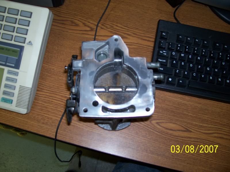
I don't know what year this TB is from, but I added the vacuum hookup for the modulator on the 97 and earlier tranny'*. All that was required was to knock a freeze plug out and drive a vac tube into the open hole.
I then mated the TB to an L36 UIM, traced the opening from the inside, and ground it out to look a little like this. I know that you can see pockets and such. The ones on the gasket surface are purely cosmetic and are not detrimental to the sealing of the gasket. The few you can see inside the TB are a end result of the welding. I could proceed to try and smooth them into nothingness, but that may end up in destroying the TB to blend them all.

And if you look inside, you can see the shaft is missing. I knocked the pin out of the shaft for the TPS, drove the shaft out of the TB entirely, and cut one half(minus a little on the edges) of the shaft out. The other side has the threads in it, so I left it alone. When reassembling the springs for the linkage, I turned the shaft 180* so that the plate has support behind it to take some load off of the screws at idle. I used a small grinding bit and knocked as much excess thread off of the screws as I could, but then that bit broke :( Counter-sunk screws will probably come in the future, but are unneccesary at this point in time. The small edges left on the shaft helped to line the plate up to it'* normal location.

A very basic and boring story, I know. Now let my put on my fire suit and release the demons to say "yay" or "nay!"
As a side note, the area after the plate was smoothed, as I noted a ridge being present originally. I used a 60 grit flap wheel, a 6" tree bur (overkill on the length) for grinding aluminum, a cutting wheel, and my excell mini die-grinder.
Took a stock L67 series 2 TB and had it welded on the gasket surface and then decked down flush.
I don't know what year this TB is from, but I added the vacuum hookup for the modulator on the 97 and earlier tranny'*. All that was required was to knock a freeze plug out and drive a vac tube into the open hole.
I then mated the TB to an L36 UIM, traced the opening from the inside, and ground it out to look a little like this. I know that you can see pockets and such. The ones on the gasket surface are purely cosmetic and are not detrimental to the sealing of the gasket. The few you can see inside the TB are a end result of the welding. I could proceed to try and smooth them into nothingness, but that may end up in destroying the TB to blend them all.
And if you look inside, you can see the shaft is missing. I knocked the pin out of the shaft for the TPS, drove the shaft out of the TB entirely, and cut one half(minus a little on the edges) of the shaft out. The other side has the threads in it, so I left it alone. When reassembling the springs for the linkage, I turned the shaft 180* so that the plate has support behind it to take some load off of the screws at idle. I used a small grinding bit and knocked as much excess thread off of the screws as I could, but then that bit broke :( Counter-sunk screws will probably come in the future, but are unneccesary at this point in time. The small edges left on the shaft helped to line the plate up to it'* normal location.
A very basic and boring story, I know. Now let my put on my fire suit and release the demons to say "yay" or "nay!"
As a side note, the area after the plate was smoothed, as I noted a ridge being present originally. I used a 60 grit flap wheel, a 6" tree bur (overkill on the length) for grinding aluminum, a cutting wheel, and my excell mini die-grinder.
 03-08-2007, 08:22 PM
#2
Senior Member
Certified GM nut

Join Date: Jul 2004
Location: New York City
Posts: 1,912
Likes: 0
Received 0 Likes
on
0 Posts

a stock N/A tb is 65 mm, with the L67 tb you have a 69mm TB. But wouldn't it have been easier to get a L36 TB have a machine shop open it to 69mm and just use the l67 TB blade.
You are now running bigger than a ZZP stage 2 TB. I am assuming this is for Big News 1 and you will be able too use a tuner to adjust the MAF readings.
And my final thought. you could also have the maf sensor shaft taken out and put in a 99+ maf sensor . like below

Now wouldn't tha be fun
You are now running bigger than a ZZP stage 2 TB. I am assuming this is for Big News 1 and you will be able too use a tuner to adjust the MAF readings.
And my final thought. you could also have the maf sensor shaft taken out and put in a 99+ maf sensor . like below
Now wouldn't tha be fun
03-08-2007, 08:32 PM
#3
Junior Member
Posts like a Ricer Type-R

Here'* some stuff to compare to. I had the luxury of a few different throttle bodies all here at the same time last year:

These are my own measurements.
More for reference:
http://www.williamwren.com/bonnevillepics/TB3.jpg
In the pic above, the Throttle plates are stacked smallest to largest, top to bottom.
L27, L67 GEN2 Series 1, L36, L67 Series 2, and L67 GEN 3 Series 1.
These are my own measurements.
More for reference:
http://www.williamwren.com/bonnevillepics/TB3.jpg
In the pic above, the Throttle plates are stacked smallest to largest, top to bottom.
L27, L67 GEN2 Series 1, L36, L67 Series 2, and L67 GEN 3 Series 1.
03-08-2007, 09:24 PM
#4
Senior Member
True Car Nut
Thread Starter
It is my experience that makes me say boring the L36 TB out to accept a 70MM plate is physically impossible. I attempted this, and used an 80 grit flap wheel to slowly remove the material. I ended up going through the sides of the TB, and at the shaft, it exposed the bearings. Magically, that TB was the one that donated the vac line hookup 
I haven't seen Wren'* TB pics for a while, but the post 96 L67 TB'* actually have a different design to the MAF post(edit: versus the L36). Less material protrudes into the inlet. While I could have cut the post out and put a 99+ sensor in, I was disinclined to do so. It presented the issue of findng a good sensor, then figuring the appropriate curves for the MAF tables. I don't know how much work was involved in that, but the fact that Ben has a good sensor in his car was enough to have me leave the post intact. I have another 96 TB coming and will sit on it until someone comes up with a 99 MAF sensor, and I feel comfortable removing the post.
Grand total on cost for this one was only $73.36(all of the welding and machine work). I guess that could be called pricey, but I took it to the best shop in town to see what they could do.... Plus, they are only about 3 blocks from where i work. It was more of a convience factor.
As an added note, the visual difference in plates alone seemed quite significant. 4 or 5mm looks like a lot when you have them on top of each other(see Wren'* pics).
I think I spent about an hour and a half making the transition on the outlet, and cutting the shaft.
03-09-2007, 12:54 AM
#5
Senior Member
True Car Nut
Join Date: Feb 2003
Location: Philly
Posts: 4,508
Likes: 0
Received 0 Likes
on
0 Posts
Nice. Aside from the maf post, it looks similar to what I did with my L67 TB. Good call on the welding.
You'll have to drill out the bolt holes to make the TB exit line up with the UIM inlet. Otherwise there will be a stepup. For what I'm talking about look here.
You'll have to drill out the bolt holes to make the TB exit line up with the UIM inlet. Otherwise there will be a stepup. For what I'm talking about look here.
 03-09-2007, 08:07 AM
#7
Senior Member
True Car Nut
Thread Starter
It'* going on an L36. I will have to have Ben stop by so I can put it back on the UIM I have. It didn't seem like it was an issue with it having to step up anywhere. Maybe this one was just lined up a little different? i don't know, but I'll check it out. As for data, that'* Ben'* job.
03-09-2007, 09:32 AM
#8
Junior Member
Posts like a Ricer Type-R
Excellent topic, fellers. Keep it up.
For the record (most reading this topic know this), the work being shown will require some not-too-easy custom tuning. Properly tuned, this TB idea can work for you. But proper tuning costs money and a great deal of knowledge/help.
Most of the pics being posted here in this topic are being posted by those who know/do tuning, or the parts are for someone that does. Just want to make sure any of the new members understand the work that still remains to get it to work with the PCM.
Carry on.....

Thread
Thread Starter
Forum
Replies
Last Post