Rear adjustment link removal
 11-02-2009, 05:10 PM
#1
Retired Senior Admin


Expert Gearhead
Thread Starter
Join Date: May 2006
Location: Sheboygan Wisconsin
Posts: 29,661
Likes: 0
Received 28 Likes
on
24 Posts


Removal Procedure
Raise and support the vehicle with jack stands
Remove the rear wheel and tire.
Remove the adjustment link retaining nut.
 This image has been resized. Click this bar to view the full image. The original image is sized 692x648.
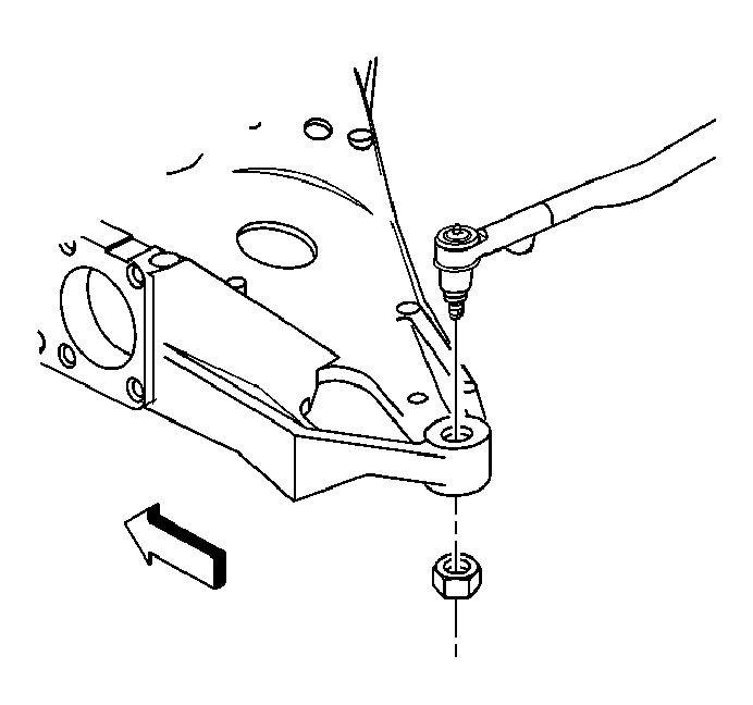
Use a knuckle separator tool, remove the adjustment link from the knuckle.
This image has been resized. Click this bar to view the full image. The original image is sized 714x655.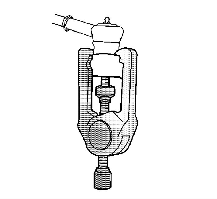
Remove the adjustment link nut and bolt.
This image has been resized. Click this bar to view the full image. The original image is sized 691x654.
Remove the adjustment link.
Installation Procedure
Install the adjustment link to the control arm.
This image has been resized. Click this bar to view the full image. The original image is sized 690x653.
Notice
Use the correct fastener in the correct location. Replacement fasteners must be the correct part number for that application. Fasteners requiring replacement or fasteners requiring the use of thread locking compound or sealant are identified in the service procedure. Do not use paints, lubricants, or corrosion inhibitors on fasteners or fastener joint surfaces unless specified. These coatings affect fastener torque and joint clamping force and may damage the fastener. Use the correct tightening sequence and specifications when installing fasteners in order to avoid damage to parts and systems.
Install the adjustment link to the control arm retaining nut.
Tighten the adjustment link to control arm to 50 N�m (36 lb ft).
This image has been resized. Click this bar to view the full image. The original image is sized 695x653.
Install the adjustment link to the support assembly.
Install the adjustment link to support bolt and nut. Tighten
Tighten the adjustment link retaining nut at the support assembly to 91 N�m (67 lb ft).
Install the tire and wheel.
Lower the vehicle.
Check toe adjustment. Refer to Wheel Alignment Specifications in Wheel Alignment.
Suspension ============ Rear
Camber ============= -0.30� � 0.50�
Camber Cross Tolerance = � 0.75�
Total Toe ============== +0.20� � 0.20�
Thrust Angle =========== 0.00� � 0.20�
Raise and support the vehicle with jack stands
Remove the rear wheel and tire.
Remove the adjustment link retaining nut.
This image has been resized. Click this bar to view the full image. The original image is sized 692x648.Use a knuckle separator tool, remove the adjustment link from the knuckle.
This image has been resized. Click this bar to view the full image. The original image is sized 714x655.Remove the adjustment link nut and bolt.
This image has been resized. Click this bar to view the full image. The original image is sized 691x654.Remove the adjustment link.
Installation Procedure
Install the adjustment link to the control arm.
This image has been resized. Click this bar to view the full image. The original image is sized 690x653.Notice
Use the correct fastener in the correct location. Replacement fasteners must be the correct part number for that application. Fasteners requiring replacement or fasteners requiring the use of thread locking compound or sealant are identified in the service procedure. Do not use paints, lubricants, or corrosion inhibitors on fasteners or fastener joint surfaces unless specified. These coatings affect fastener torque and joint clamping force and may damage the fastener. Use the correct tightening sequence and specifications when installing fasteners in order to avoid damage to parts and systems.
Install the adjustment link to the control arm retaining nut.
Tighten the adjustment link to control arm to 50 N�m (36 lb ft).
This image has been resized. Click this bar to view the full image. The original image is sized 695x653.Install the adjustment link to the support assembly.
Install the adjustment link to support bolt and nut. Tighten
Tighten the adjustment link retaining nut at the support assembly to 91 N�m (67 lb ft).
Install the tire and wheel.
Lower the vehicle.
Check toe adjustment. Refer to Wheel Alignment Specifications in Wheel Alignment.
Suspension ============ Rear
Camber ============= -0.30� � 0.50�
Camber Cross Tolerance = � 0.75�
Total Toe ============== +0.20� � 0.20�
Thrust Angle =========== 0.00� � 0.20�


Thread
Thread Starter
Forum
Replies
Last Post
ShadeTree
Buick
0
04-11-2015 11:51 AM