how do you run your ipod/aux in?


 11-05-2011, 05:17 PM
#12
Senior Member
Certified GM nut
Certified GM nut
Thread Starter
tutorial time.
this is a tutorial on how to wire up the auxillary port.
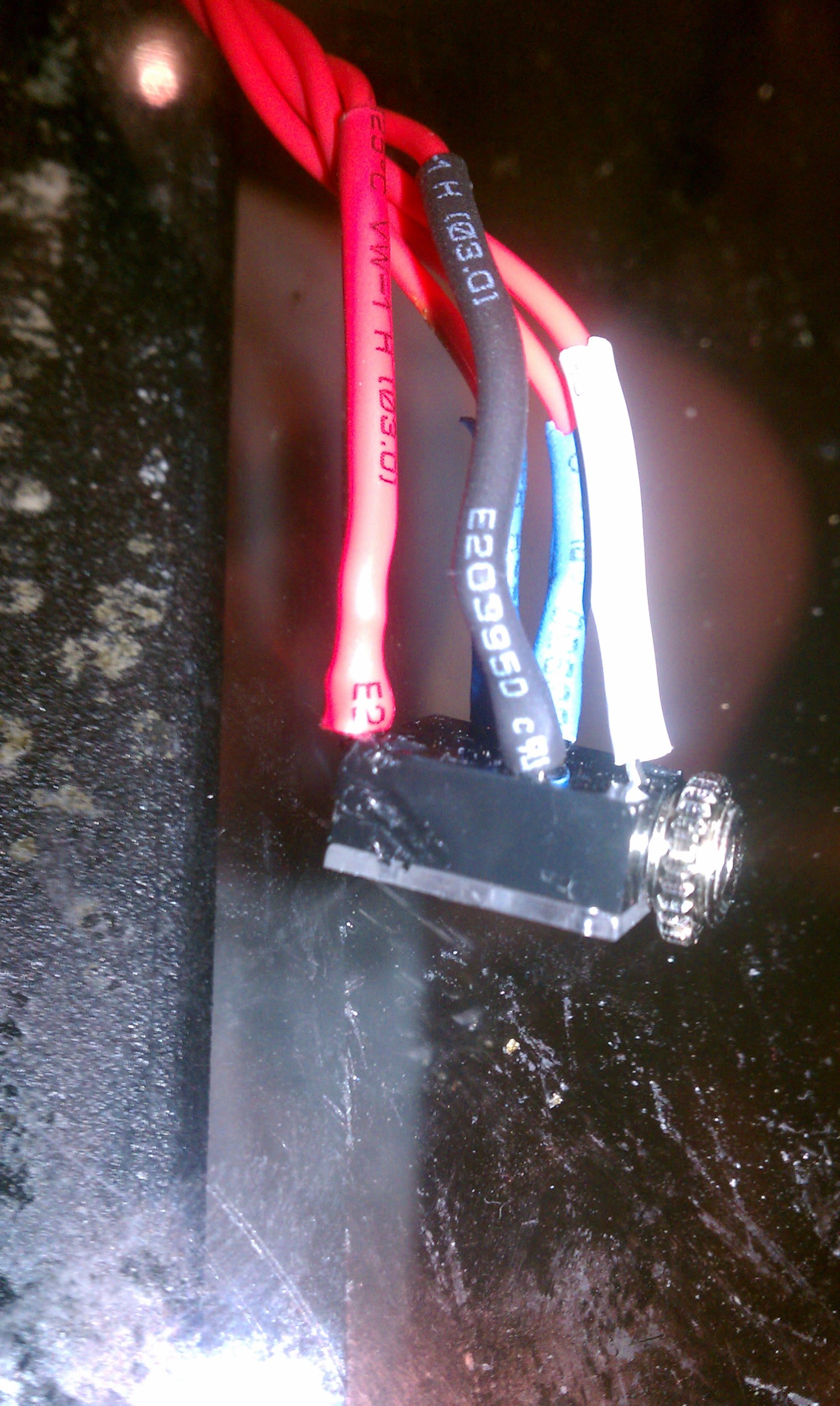
before you do anything with the stereo, get 5 lengths of wire and solder them to the 5 pins on the jack. make sure to label the wires to match the diagram'* number key. itll make the rest of this alot easier.
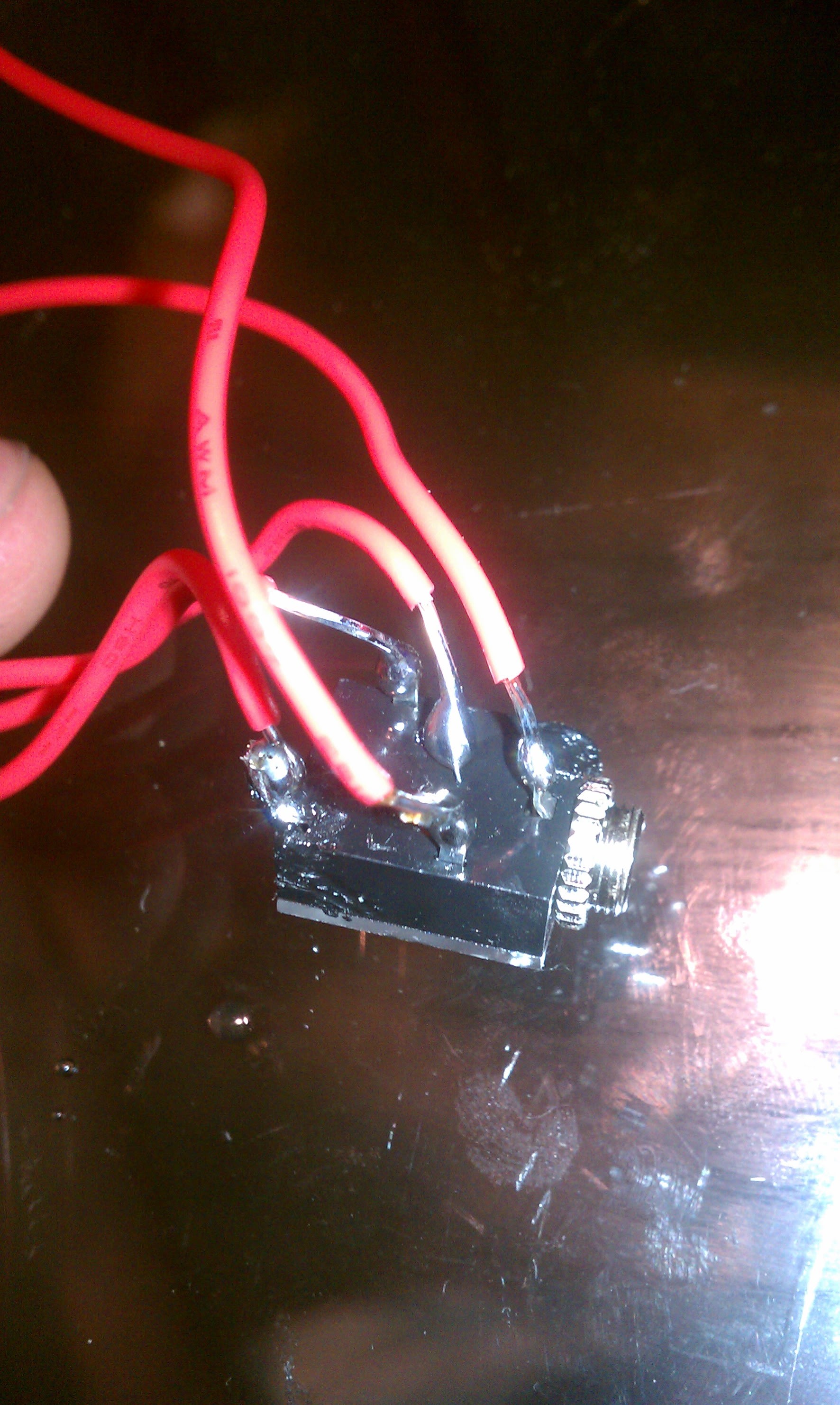
make sure to shrink wrap the connections after also.
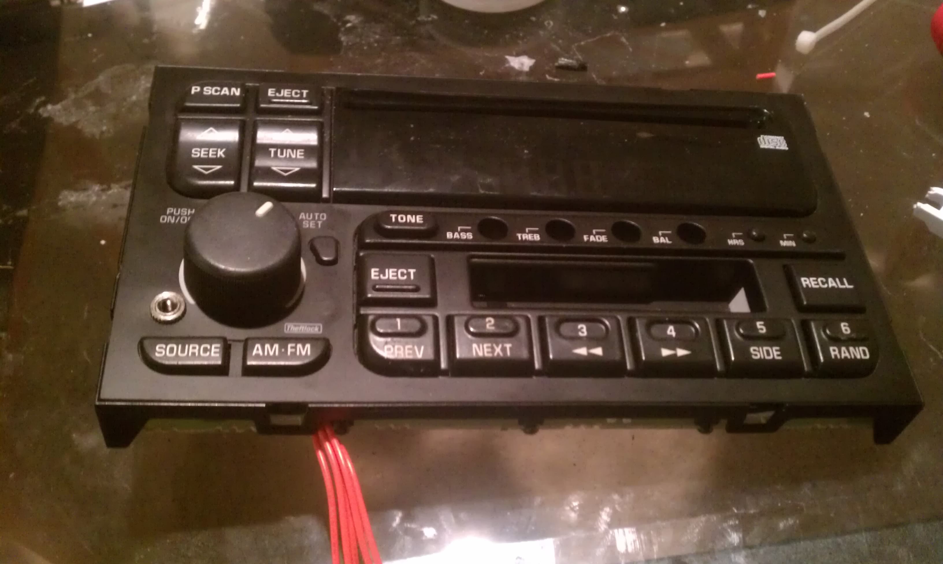
remove the deck from your car. if you dont know how, search around the forum.
once you have the deck out, you need to remove the heatsink on the side. there are 4-5 screws. one will be longer than all the others. make sure to section all screws out in baggies or an ice cube tray like i used so you know what parts they go to. because all the screws look the same but they vary slightly in thread count and it makes it really annoying to put back together.
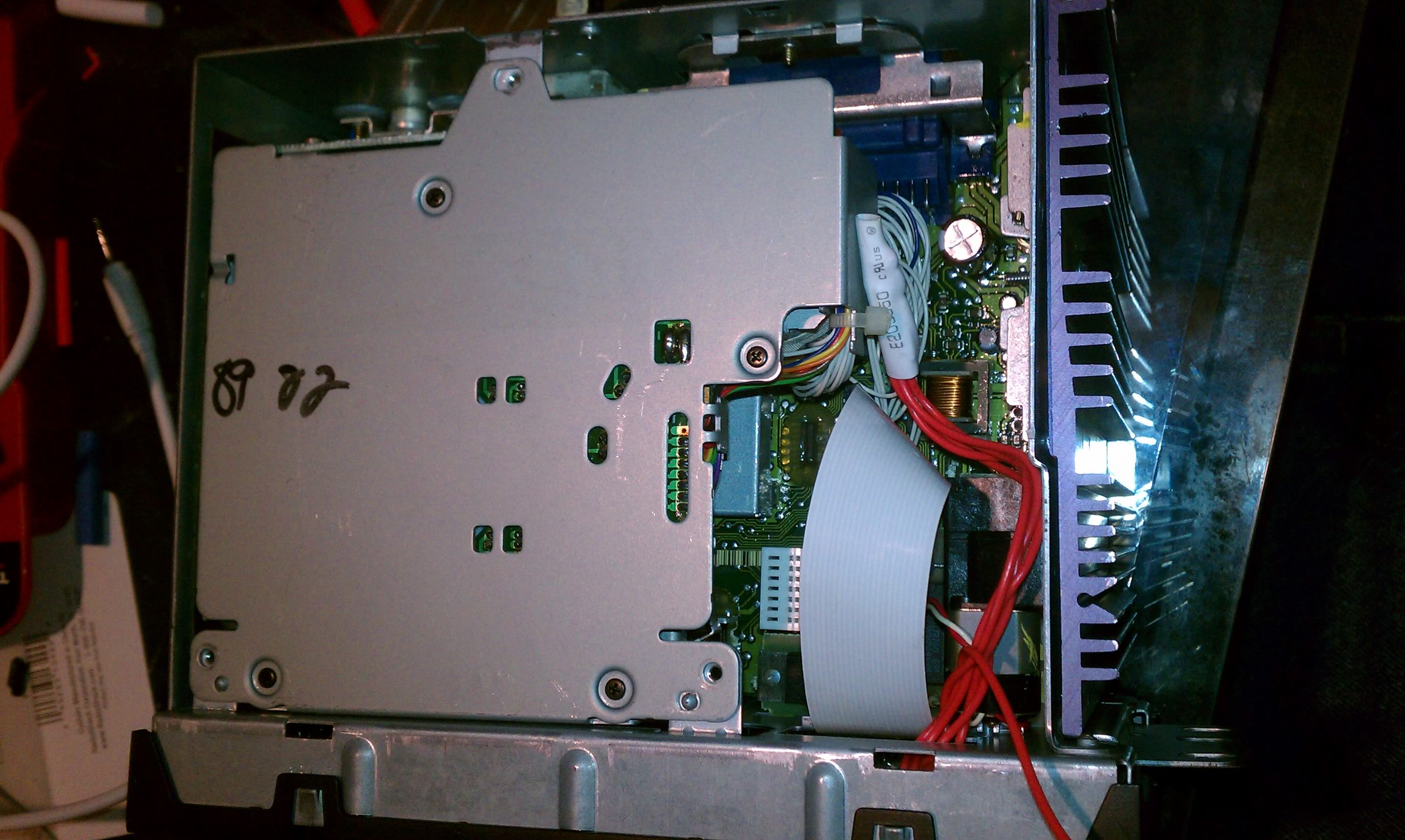
after you have the heatsink off, flip the stereo upide down, and look at the back. on the bottom (now top side) of the back there is one single screw holding the bottom (now top) cover on. remove it, and then pry the cover off.
you will then be looking at the tape deck. its held on with 3 screws. remove them, then pull out the 2 ribbon connectors that hook the tape deck to the main board. set it aside.
unclip the faceplate with a flathead around all 4 sides. make sure your volume **** is removed or it wont slide out. be careful not to tear the faceplate'* ribbon cable. pull it straight up out of the main board.
once the faceplate is off, remove the 800 or so phillips head screws on the back of the faceplate, and pull the circuit board straight up and put it on a non static heavy surface.
now is a good time to look at the backside of the switches, or better yet take a picture. then remove everything that is loose and put it someplace flat away from pets and small children. i swear there are about 100 pieces.
if you mount your aux port where i mounted mine, you will need to take a considerable chunk out of the clear light transmitting plastic to accomodate the switch. i cut mine just enough to where my lighting isnt affected. i also had to cut out one of the studs that the circuit boards screw uses.
then (obviously) drill out the hole in the correct spot, starting with small bits and going up gradually so you dont tear the 10+ year old plastic.
once your jack is mounted, make sure there is no visible solder that can contact the circuit board.
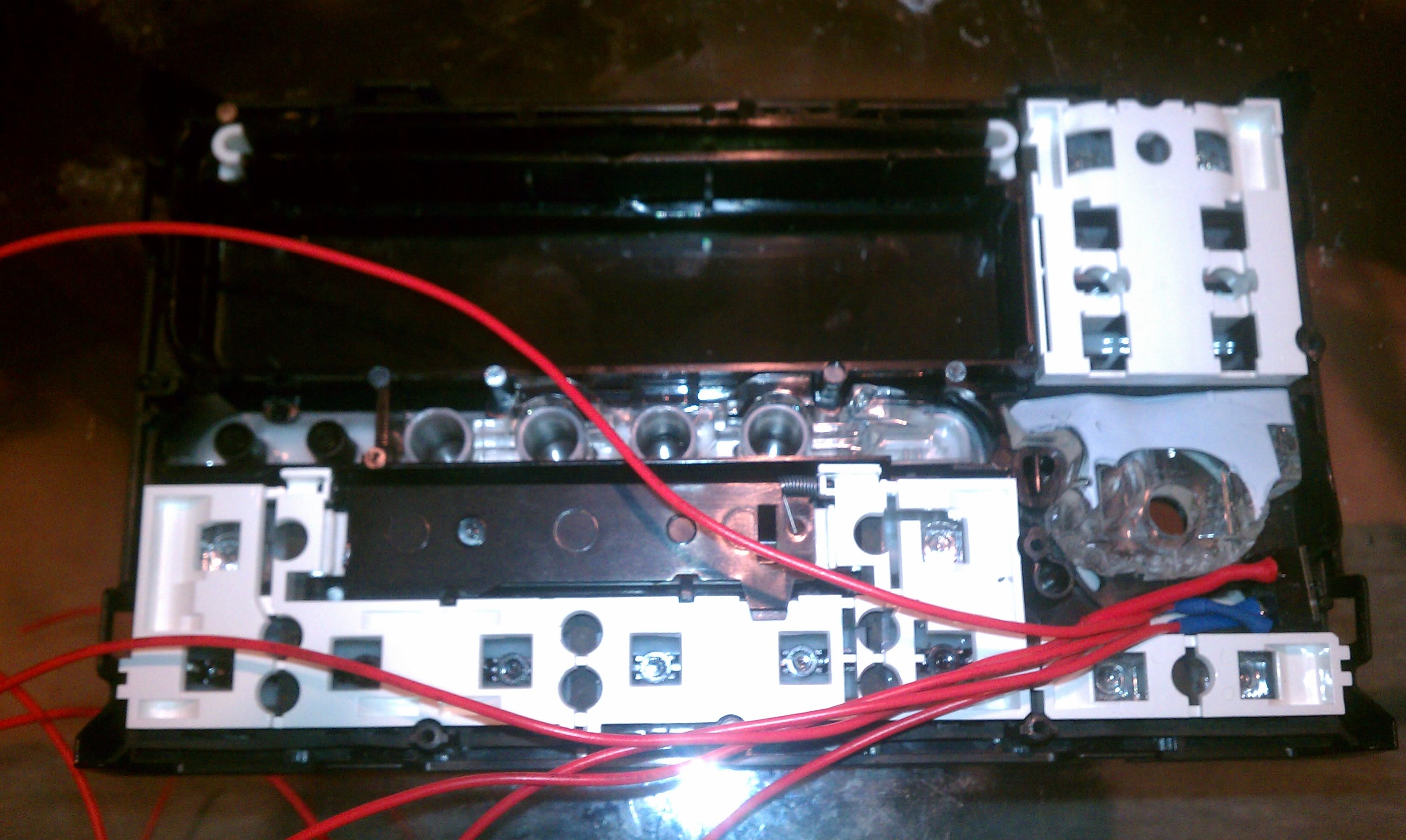
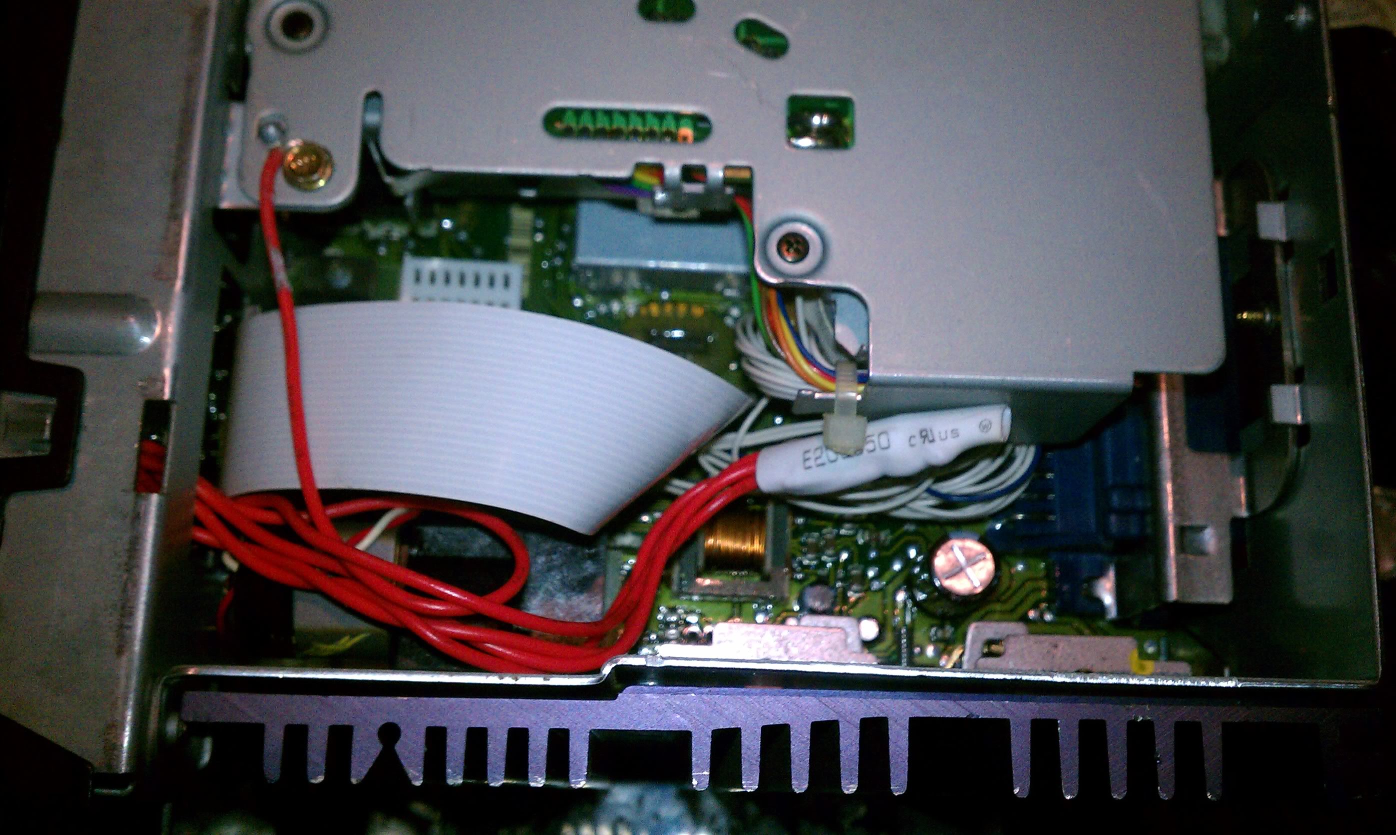
i used shrink wrap to hold the wires together, (not pictured) and ditched the useless piece of plastic around those 2 switches. if you route your wires like i did mine you shouldnt have any issues mounting the circuit board.
after test fitting you can go on to attaching the wires to the tape deck. i routed my wires through the stereos case with the ribbon cable.
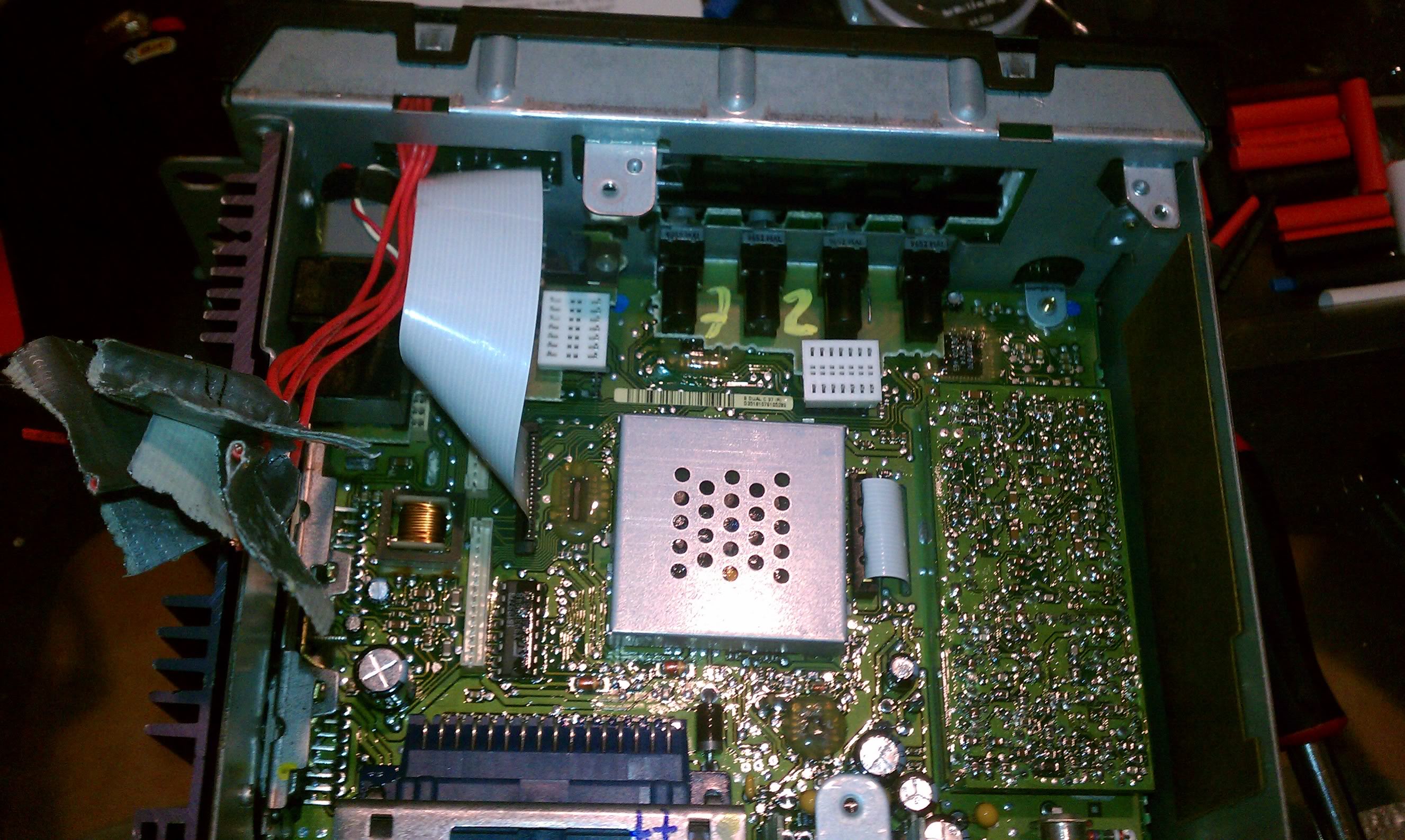
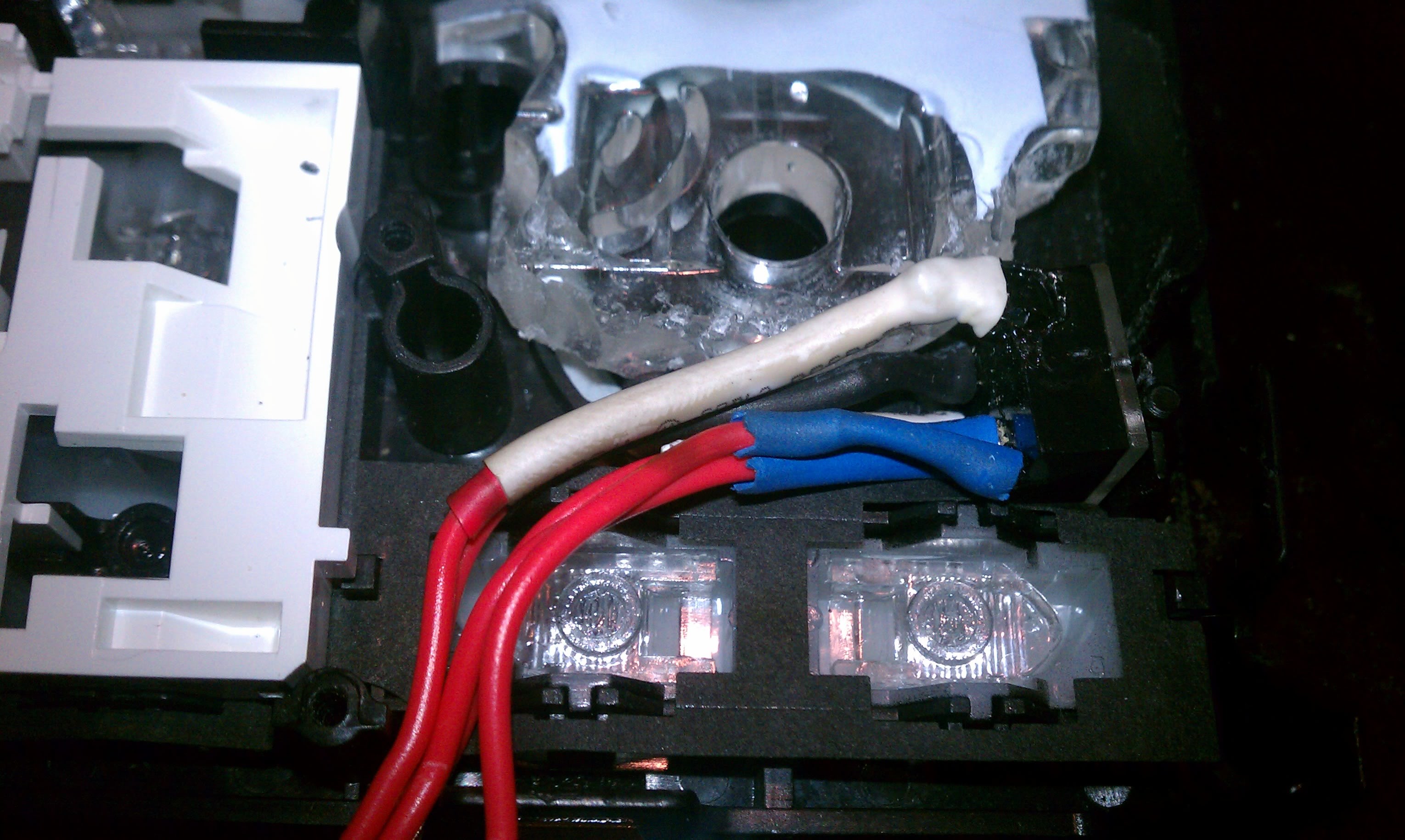
go ahead and cut the middle of wires 5 and 7, on the 7 pin connector. the blue one being number 1. number 7 is your left speaker and number 5 is your right.
if you want to keep the functionality of your tape deck, attach the wires that arent going to the connector to the normally closed pins on your connector. #4(right) and #3(left) on the switch i used. radioshack part number 274-246 http://www.radioshack.com/product/in...ductId=2103451
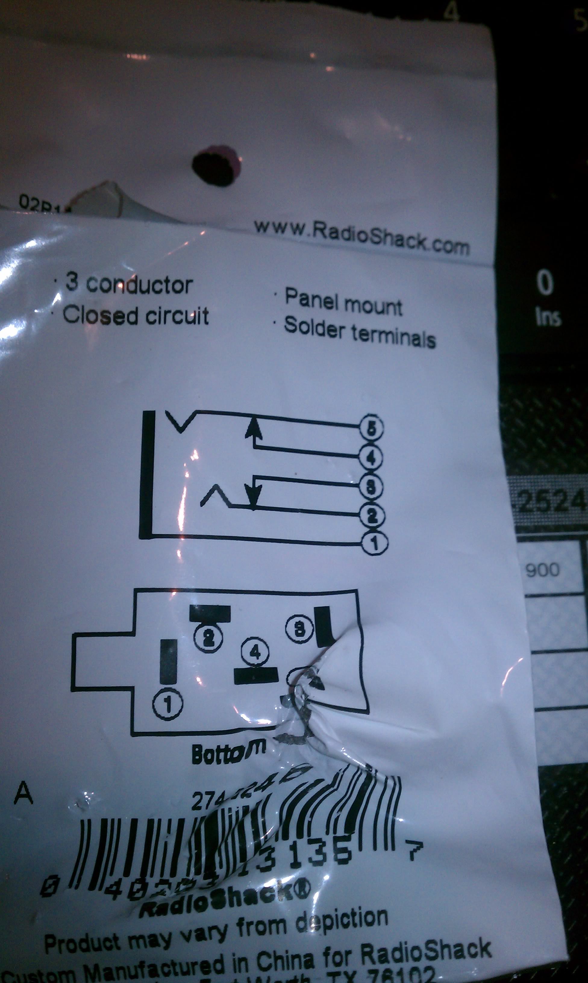
now, for the wires going to the ribbon connector, attach pin7 to #5 on the jack. (thats the normally open one) pin 5 goes to #2 (see last pic)
#1 on the jack, you just need to find a ground. i got a nail file and sanded the paint down on the cassette deck mounting screw hole and pinched the wire when i reinstalled the deck.
at this point, you can reinstall the deck and its connectors.
if you have some large enough i used some spare shrink wrap to bundle all the wires together to just make it neater. a small zip tie would work just as well.
at this point you can reinstall the bottom panel and install in your car.
you will now have cd quality audio instead of those stupid tape adapters.
heres a demo of how it works
[YT]http://www.youtube.com/watch?v=BrGkucd15Hs[/YT]
this is a tutorial on how to wire up the auxillary port.
before you do anything with the stereo, get 5 lengths of wire and solder them to the 5 pins on the jack. make sure to label the wires to match the diagram'* number key. itll make the rest of this alot easier.
make sure to shrink wrap the connections after also.
remove the deck from your car. if you dont know how, search around the forum.
once you have the deck out, you need to remove the heatsink on the side. there are 4-5 screws. one will be longer than all the others. make sure to section all screws out in baggies or an ice cube tray like i used so you know what parts they go to. because all the screws look the same but they vary slightly in thread count and it makes it really annoying to put back together.
after you have the heatsink off, flip the stereo upide down, and look at the back. on the bottom (now top side) of the back there is one single screw holding the bottom (now top) cover on. remove it, and then pry the cover off.
you will then be looking at the tape deck. its held on with 3 screws. remove them, then pull out the 2 ribbon connectors that hook the tape deck to the main board. set it aside.
unclip the faceplate with a flathead around all 4 sides. make sure your volume **** is removed or it wont slide out. be careful not to tear the faceplate'* ribbon cable. pull it straight up out of the main board.
once the faceplate is off, remove the 800 or so phillips head screws on the back of the faceplate, and pull the circuit board straight up and put it on a non static heavy surface.
now is a good time to look at the backside of the switches, or better yet take a picture. then remove everything that is loose and put it someplace flat away from pets and small children. i swear there are about 100 pieces.
if you mount your aux port where i mounted mine, you will need to take a considerable chunk out of the clear light transmitting plastic to accomodate the switch. i cut mine just enough to where my lighting isnt affected. i also had to cut out one of the studs that the circuit boards screw uses.
then (obviously) drill out the hole in the correct spot, starting with small bits and going up gradually so you dont tear the 10+ year old plastic.
once your jack is mounted, make sure there is no visible solder that can contact the circuit board.
i used shrink wrap to hold the wires together, (not pictured) and ditched the useless piece of plastic around those 2 switches. if you route your wires like i did mine you shouldnt have any issues mounting the circuit board.
after test fitting you can go on to attaching the wires to the tape deck. i routed my wires through the stereos case with the ribbon cable.
go ahead and cut the middle of wires 5 and 7, on the 7 pin connector. the blue one being number 1. number 7 is your left speaker and number 5 is your right.
if you want to keep the functionality of your tape deck, attach the wires that arent going to the connector to the normally closed pins on your connector. #4(right) and #3(left) on the switch i used. radioshack part number 274-246 http://www.radioshack.com/product/in...ductId=2103451
now, for the wires going to the ribbon connector, attach pin7 to #5 on the jack. (thats the normally open one) pin 5 goes to #2 (see last pic)
#1 on the jack, you just need to find a ground. i got a nail file and sanded the paint down on the cassette deck mounting screw hole and pinched the wire when i reinstalled the deck.
at this point, you can reinstall the deck and its connectors.
if you have some large enough i used some spare shrink wrap to bundle all the wires together to just make it neater. a small zip tie would work just as well.
at this point you can reinstall the bottom panel and install in your car.
you will now have cd quality audio instead of those stupid tape adapters.
heres a demo of how it works
[YT]http://www.youtube.com/watch?v=BrGkucd15Hs[/YT]
11-05-2011, 06:16 PM
#14
Senior Member
Certified GM nut
Certified GM nut
Thread Starter
yea, it was pretty simple. it was just a bitch carving that thick assed clear piece.
11-05-2011, 06:26 PM
#15
Senior Member
Certified GM nut
I bet. haha. Did you just use a knife and slowly cut your way into it? You didn't happen to notice what the lights were like for the buttons and everything were like, did you? Most of my lights are out, and it looks bad at night.
11-05-2011, 06:30 PM
#16
Senior Member
Certified GM nut
Certified GM nut
Thread Starter
all it is is little leds soldered in with little blue condoms lol. wouldnt be too hard to replace. and no, i went at it the brute force way. literally just used my cheap *** clearance wire strippers to cmash the plastic and it shattered like a piece of ice lol.
11-05-2011, 06:36 PM
#17
Senior Member
Certified GM nut
haha. Well, like they say, there'* more than one way to skin a cat. haha. If I get around to doing this, I'll try to cut it. With my luck, I'll end up cutting my hand open, or doing a lot more damage.
Do you know what size they are? I'd like to pick up some blue led'* to replace all of them, to keep my blue theme going if possible..
Do you know what size they are? I'd like to pick up some blue led'* to replace all of them, to keep my blue theme going if possible..
11-05-2011, 08:34 PM
#18
Senior Member
Certified GM nut
Certified GM nut
Thread Starter
well, my climate control used these 12.0v 50mA T1 type bulbs from radio shack (part #272-1154) they looked the same in the stereo.
11-08-2011, 12:08 AM
#19
Senior Member
True Car Nut
Join Date: Jan 2011
Location: Michigan
Posts: 3,344
Likes: 0
Received 0 Likes
on
0 Posts

i plug my ipod with an aux cord into my JVC and control the stereo with my ipod.. i dont really fumble around with volume + song switching too much if i need to skip i just hit next on the ipod, if i need to turn it down i just swipe the **** real quick


