Where do these go Part II (Engine Wiring harnesses)
 05-24-2012, 08:11 PM
#1
Member
Posts like a V-Tak
Thread Starter

Join Date: Sep 2005
Location: Tempe, AZ
Posts: 73
Likes: 0
Received 0 Likes
on
0 Posts

Okay, so I've done my best to do a search on this board and many others, but I couldn't find a really comprehensive writeup on the engine wiring. If one exists or someone has pictures with labels from their own rebuild I would be greatly indebted.
So I have an idea of where the fuel injector harnesses go, luckily they are labeled by number to the respective cylinders (please correct me if I am wrong). I realize a lot of the harnesses should just fit due to proximity, but I just want to be extra sure before I start trying to force prongs where they shouldn't go. Like I've mentioned before, nothing was labeled when this engine was pulled apart (which is a mistake I would never make again)
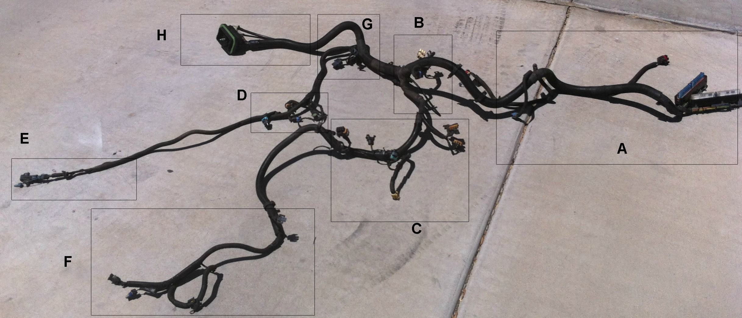
Here is a full view of the wiring harness, with my arbitrary and poorly designed divisions :-p
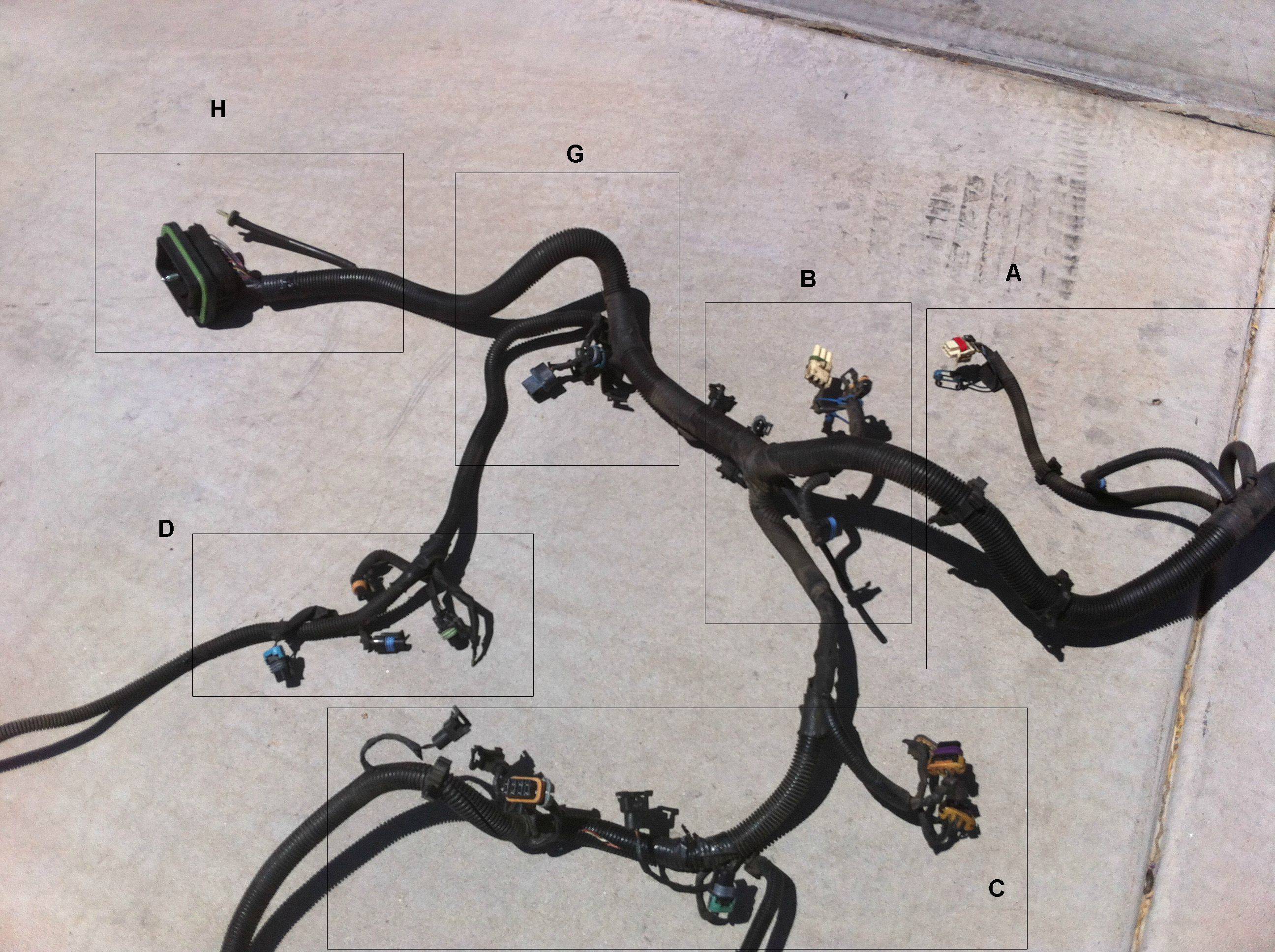
Closeup of the middle
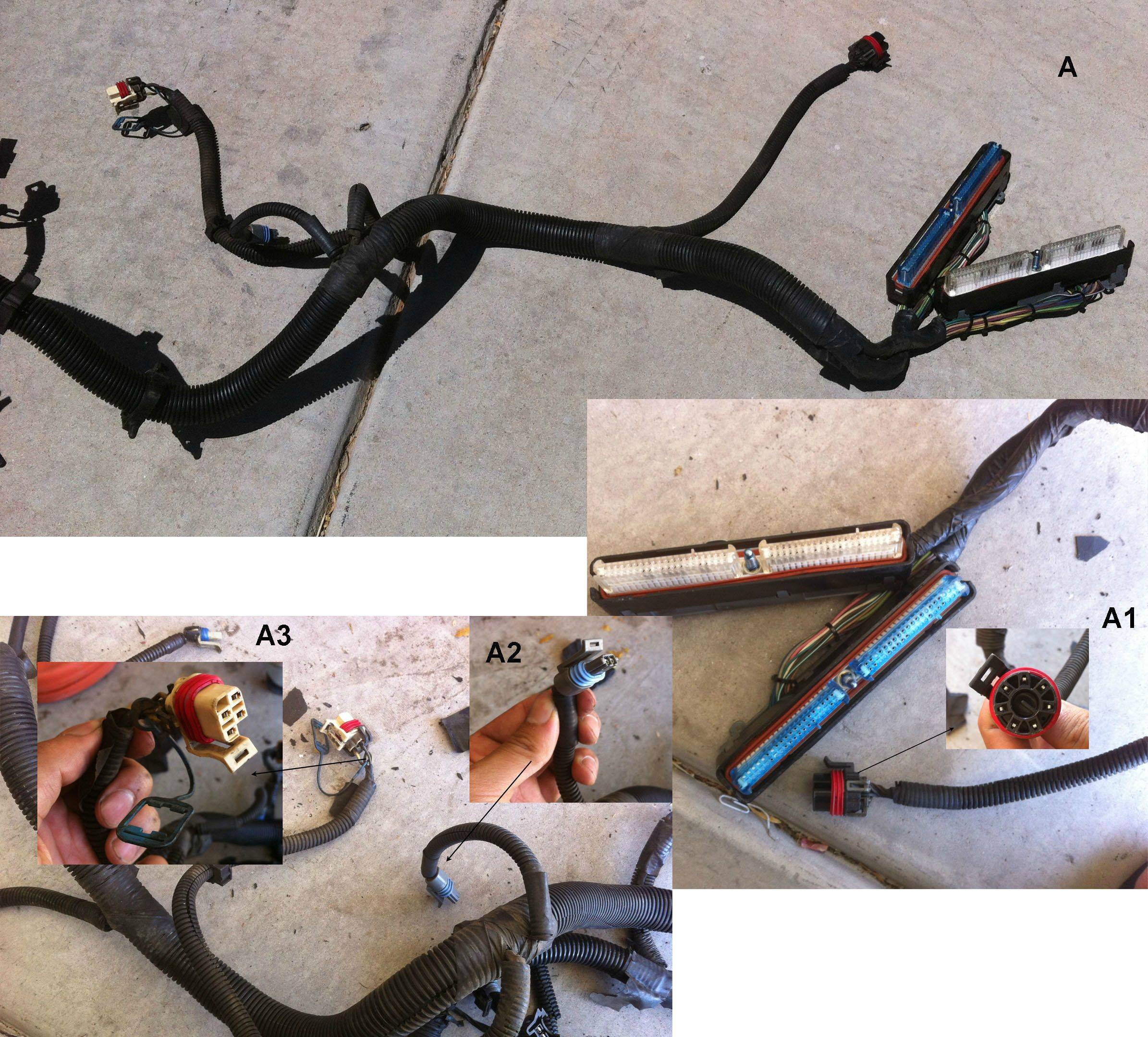
Part A, which extends from the PCM I believe. I've kind of separated each specific plug by letter and number and these are the ones I am not entirely sure of.
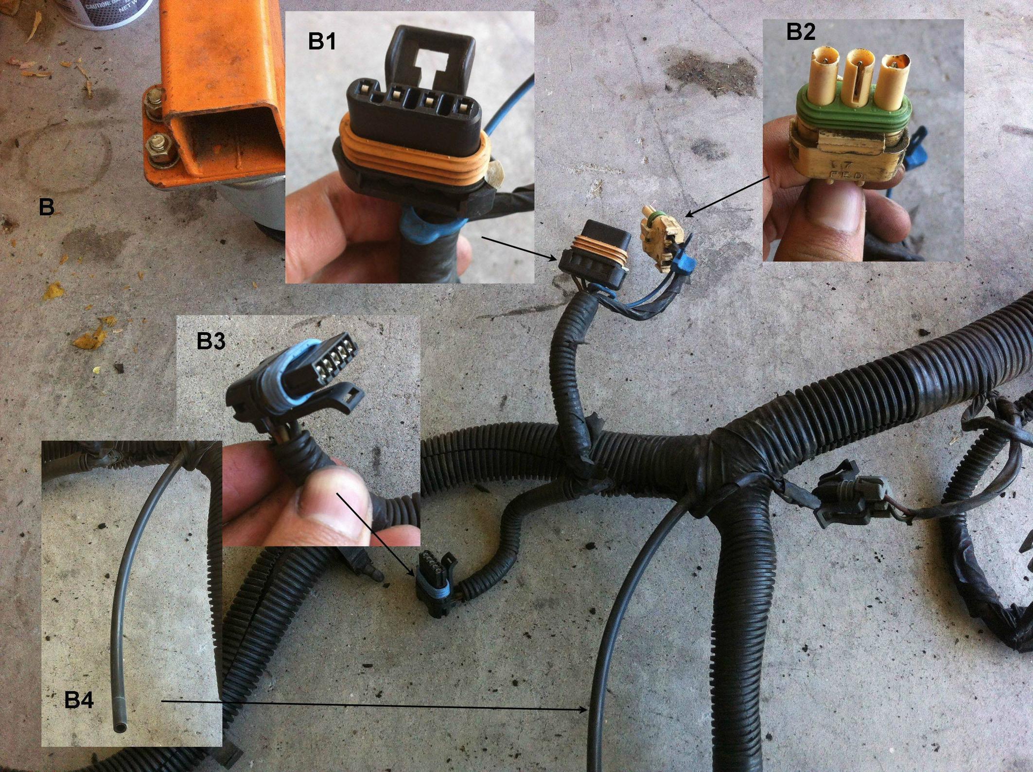
Part B
Zoom out of C, with random plug at bottom I forgot to label, we can call it U1

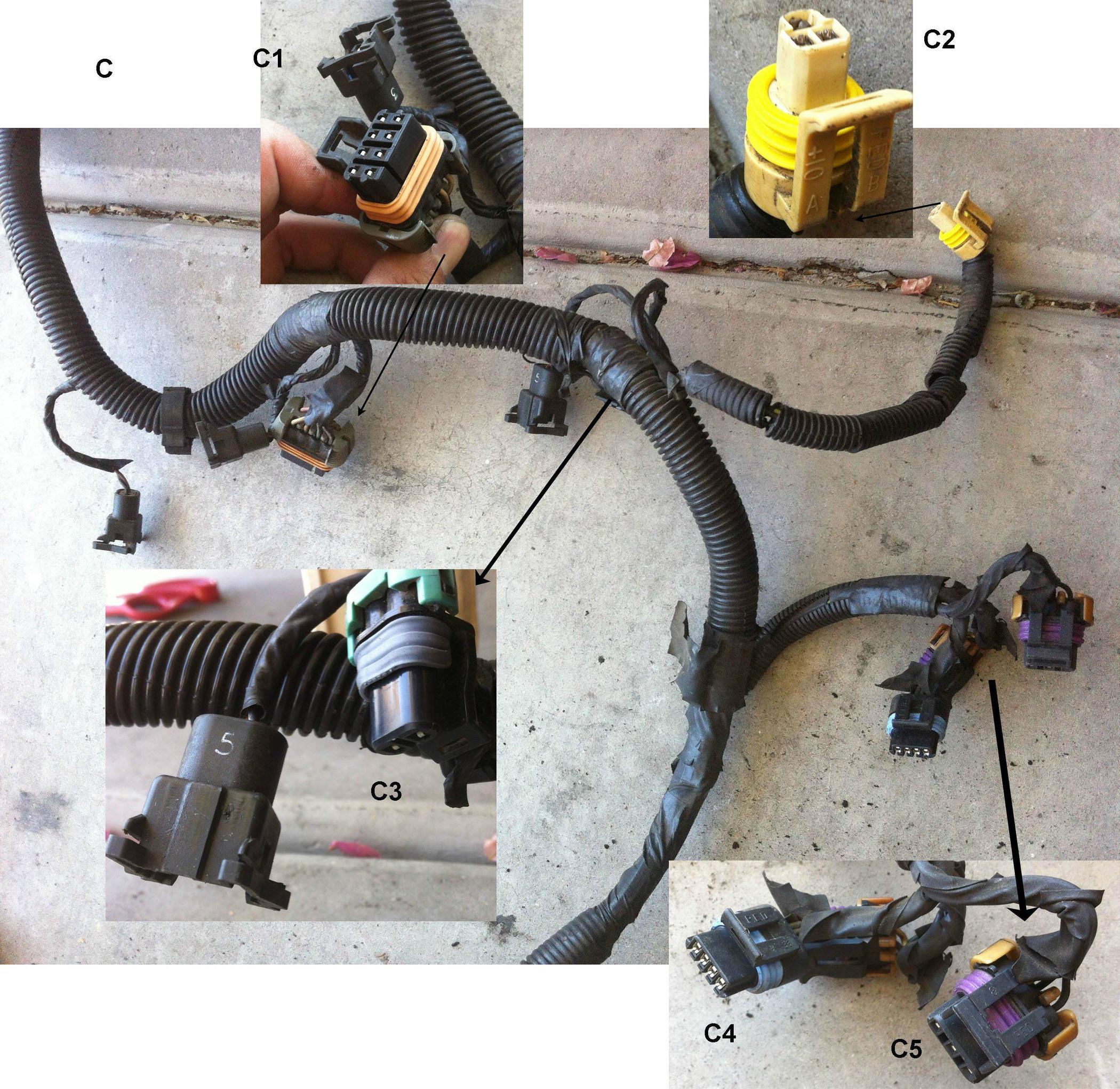
Part C
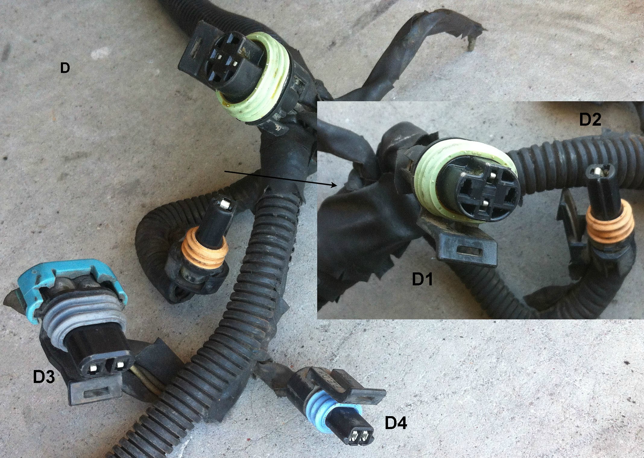
Part D
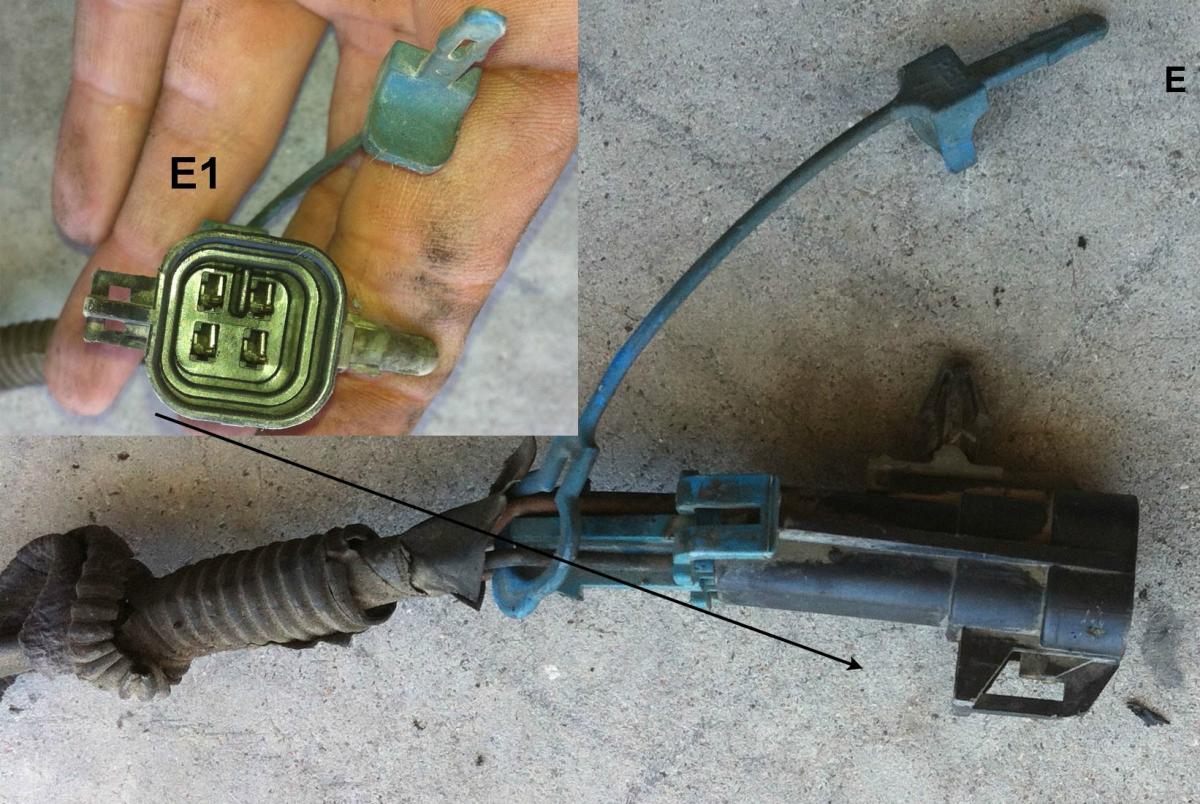
Part E
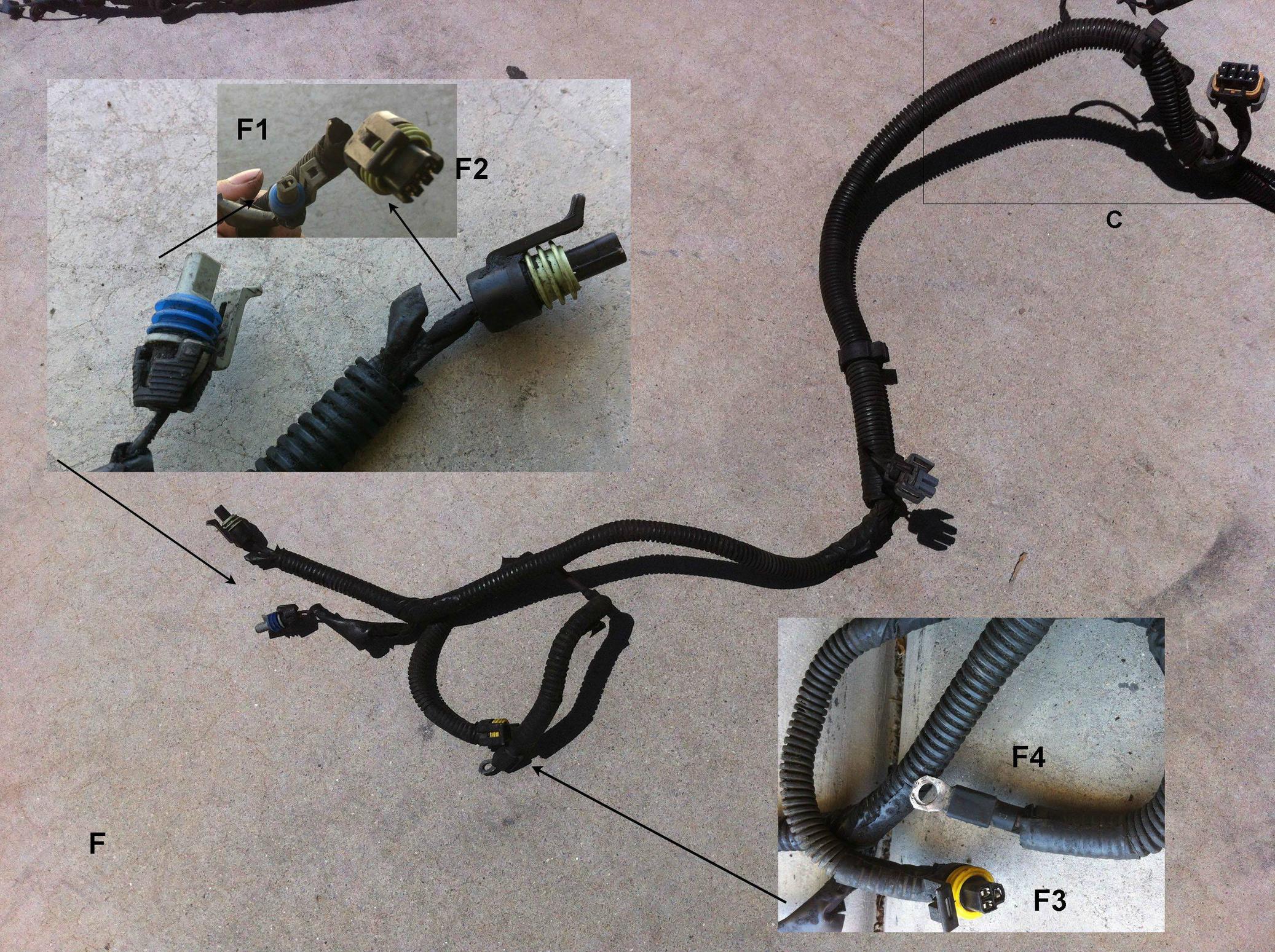
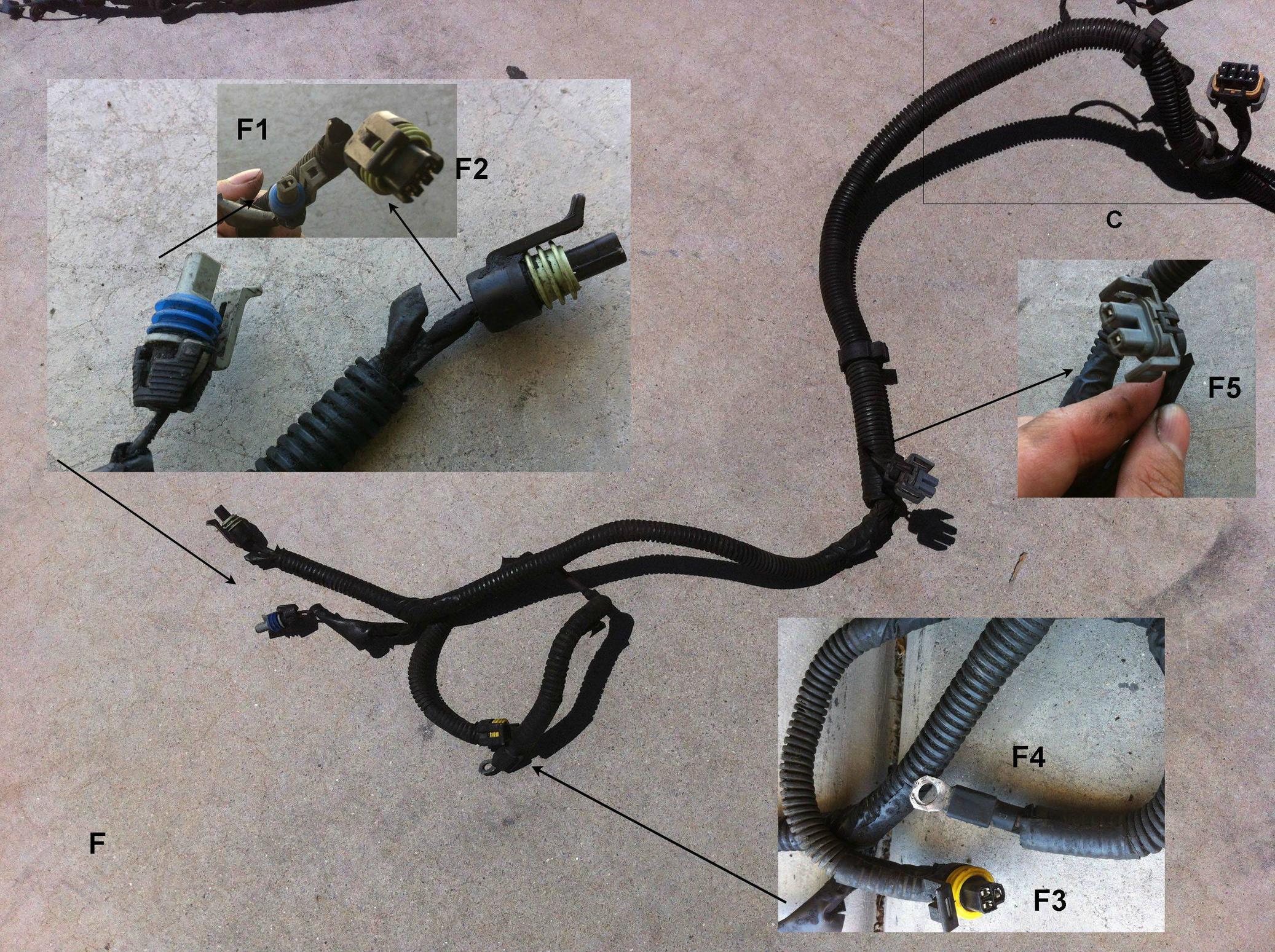
Part F, Again, you can see where U1 bridges C and F
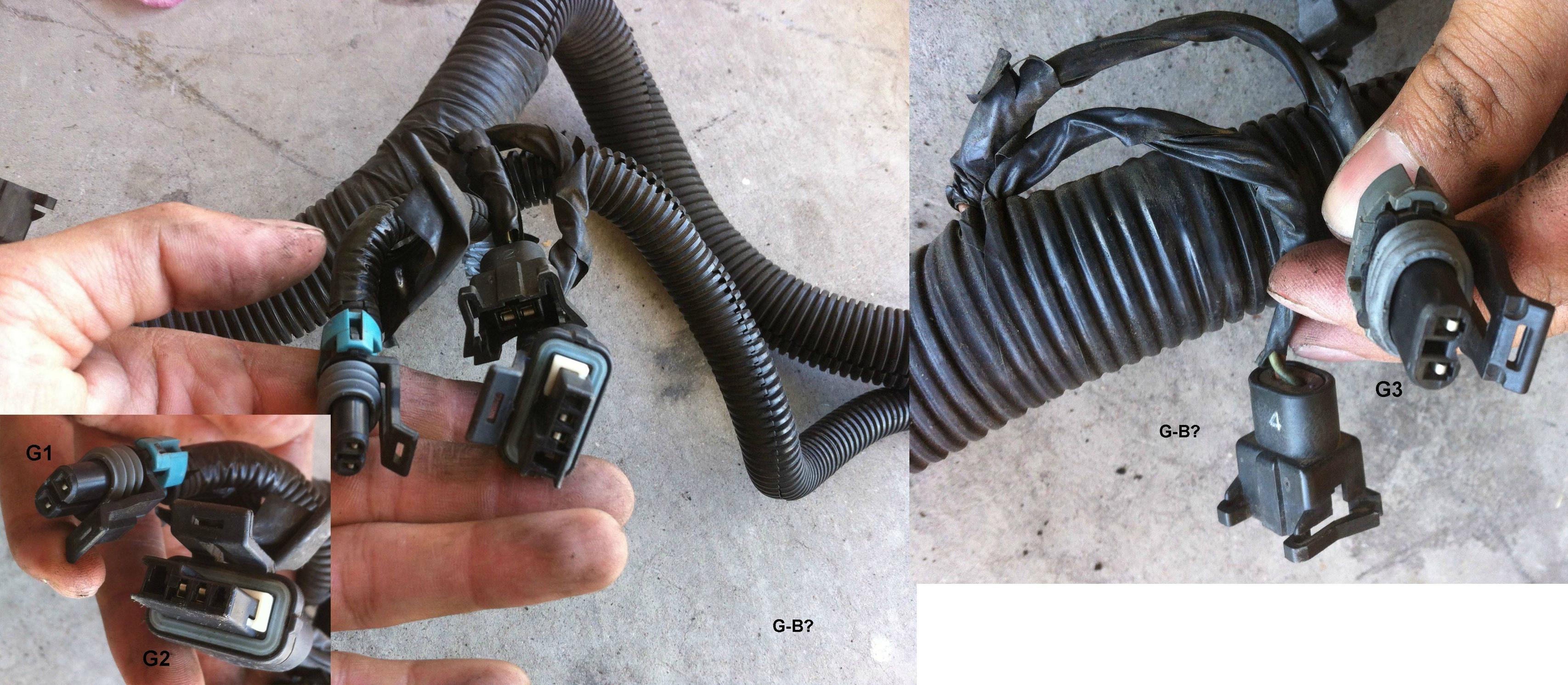
Part G, if you look closely, fuel injector 2 extends on the left from the two G1 and G2, and fuel inject 4 extends from the same root as the single G3
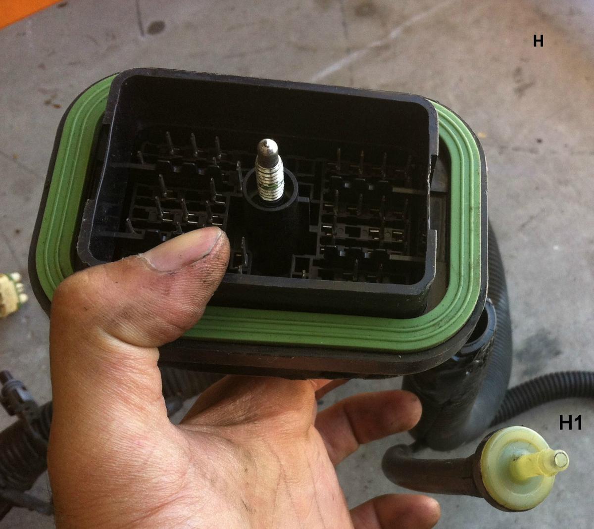
Part H, I am guessing the big one goes to the back right section close to the firewall, but not sure about that vacuum looking piece (H1)
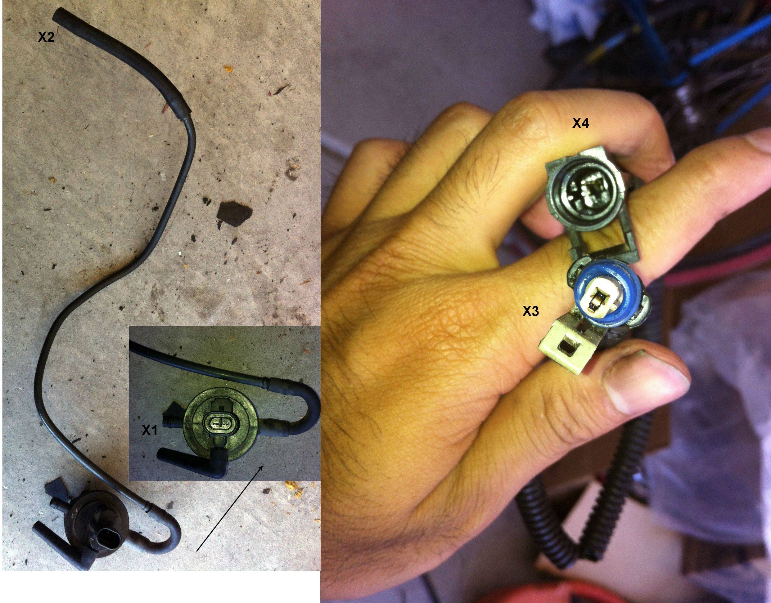
This I am calling part X, these guys are just separate from the big loom altogether.
Anyway, if anyone happens to have notes, pictures, or even remembers where all of these go I would be forever gracious!!
So I have an idea of where the fuel injector harnesses go, luckily they are labeled by number to the respective cylinders (please correct me if I am wrong). I realize a lot of the harnesses should just fit due to proximity, but I just want to be extra sure before I start trying to force prongs where they shouldn't go. Like I've mentioned before, nothing was labeled when this engine was pulled apart (which is a mistake I would never make again)
Here is a full view of the wiring harness, with my arbitrary and poorly designed divisions :-p
Closeup of the middle
Part A, which extends from the PCM I believe. I've kind of separated each specific plug by letter and number and these are the ones I am not entirely sure of.
Part B
Zoom out of C, with random plug at bottom I forgot to label, we can call it U1
Part C
Part D
Part E
Part F, Again, you can see where U1 bridges C and F
Part G, if you look closely, fuel injector 2 extends on the left from the two G1 and G2, and fuel inject 4 extends from the same root as the single G3
Part H, I am guessing the big one goes to the back right section close to the firewall, but not sure about that vacuum looking piece (H1)
This I am calling part X, these guys are just separate from the big loom altogether.
Anyway, if anyone happens to have notes, pictures, or even remembers where all of these go I would be forever gracious!!
 05-24-2012, 09:31 PM
#2
Retired


Certified Car Nut


Holy cow!!! How long did it take you to do up all those pictures????!?!?! Anyway...I have done 95'*, 96'* and 97'*. As you already mentioned the injectors. Lay the harness on top of the engine with the injector connectors near the injectors. I BELIEVE, there are no 2 alike connectors on the engine besides the 2 knock sensors. Just start pluggin stuff in. If you find an odd ball connector, let us know.
Remember. Leave that oil pressure sensor OUT until you put that engine in.
These pics might help.
https://www.gmforum.com/showthread.p...reference+pics
Remember. Leave that oil pressure sensor OUT until you put that engine in.
These pics might help.
https://www.gmforum.com/showthread.p...reference+pics
__________________
Retired Administrator
2002 *-10 5.7 V8
2023 Jeep Rubicon Diesel
Retired Administrator
2002 *-10 5.7 V8
2023 Jeep Rubicon Diesel
05-25-2012, 07:48 AM
#3
DINOSAURUS BOOSTUS
Expert Gearhead
I looked at your pics and think this should be come stickied. Based on the harness (you didn't say what it was for) I can tell this is a 96 H body SC car.
Ready..this is all from from my head and you can trust it.
A Pcm connectors (match blue to the blue label on pcm and clear to clear)
A1. Trans connector for a 4T60E
A2. Power steering connection (magnasteer)
A3. Park neutral safety switch (on top of trans)
B1. Front O2 sensor (96 was a flat connector like this, 97 would have been a square)
B2. Map sensor (rear of engine)
B3. Looks like a 10 wire, but is in the right place to be EGR. If it'* 5 wires..it'* EGR
B4. Vacuum line (connects to center port on top of SC, is the other end to H1)
C1. ICM/Crank/Cam harness (other side typically stays on the motor. Connects right by FPR)
C2. Coolant temp sensor (under top rad hose connection at engine)
C3. BCS or boost control soleniod (next to #5 injector)
C4. IAC
C5. Either MAF or TPS connector, oddly there should be two of these with a purple seal on them. One for the maf, one for tps. You appear to be missing a connector in the C'*.
D1. Oil pressure sensor (back passenger side of motor above oil filter)
D2. Rear knock sensor (Connects to X4 to give you a pigtail for installation, makes connection to rear knock sensor much easier)
D3. Not 100% on this one, I believe the power steering pump in that year had a connection and this should be it.
D4. VSS akd Vehicle Speed Sensor (connection on diff cover of transmission by passenger inner cv boot.)
E1. Rear O2 sensor (this wire runs into a metal shield along the exhaust tunnel under the car.
F1. Front knock sensor (located between AC compressor and starter)
F2. Oil level sensor (front of oil pan by ac/starter)
F3. AC high pressure switch (also by AC compressor)
F4. Starter soleniod (small bolt on starter soleniod)
You should have one more F connector for the AC compressor.
G1. Either the evap purge valve or the evap switch (location behind alternator)
G2. Alternator
G3. Same as G1 (if G1 is valve, this is switch)
H. C100 main electrical harness connection that connects near passenger strut tower on firewall.
H1. Other end of B4, it connects to the vac hose you'll find near H
X1. This is the evap purge valve.
You should also have a rectangular black box that would hook to the empty port (not the L hose, the other open port) The rectangle is the evap purge switch.
X2. On the front driverside end of the head, there should be a metal tube bolted up. This hose connects there. if you don't have the tube, run this hose to the evap canister labeled evap.
X3. Rear knock sensor connection end of the rear knock sensor pigtail. The pigtail is this small harness piece you have labeled X3 and X4
X4. End of harness the connects to D2. When lowering in the motor w/o the harness on it, this small pigtail makes it easy to connect to the rear knock sensor because it is hidden up between the engine and trans.
In summation, you are missing two connectors. One is either your TPS or MAF sensor (depending on how it'* keyed) and the other is the AC compressor connector (two pin) that controls the compressor on/off.
Yep, I may have done this too many times.
05-25-2012, 07:54 AM
#4
Retired
Certified Car Nut
Forget Stickying it Bill, me thinks this would be a good Techinfo article.
__________________
Retired Administrator
2002 *-10 5.7 V8
2023 Jeep Rubicon Diesel
Retired Administrator
2002 *-10 5.7 V8
2023 Jeep Rubicon Diesel
05-25-2012, 08:08 AM
#5
DINOSAURUS BOOSTUS
Expert Gearhead
yeah....that'* what I was thinking Mike. Some forums are sticky..some are Tech. You got me. Now if we took the pics and added the verbage for the pic right below it.. and er uh..on those two connectors, we have him find them and those get labeled as well.
PS..Did I tell ya, it'* a disease that I can tell you the car, make and model based off a wiring harness.
PS..Did I tell ya, it'* a disease that I can tell you the car, make and model based off a wiring harness.
05-25-2012, 08:17 AM
#6
Retired
Certified Car Nut
Not a disease Bill, an obsession. In a good way.
__________________
Retired Administrator
2002 *-10 5.7 V8
2023 Jeep Rubicon Diesel
Retired Administrator
2002 *-10 5.7 V8
2023 Jeep Rubicon Diesel
05-25-2012, 01:55 PM
#7
Member
Posts like a V-Tak
Thread Starter
Join Date: Sep 2005
Location: Tempe, AZ
Posts: 73
Likes: 0
Received 0 Likes
on
0 Posts
05-28-2012, 06:43 AM
#8
Member
Posts like a V-Tak
Thread Starter
Join Date: Sep 2005
Location: Tempe, AZ
Posts: 73
Likes: 0
Received 0 Likes
on
0 Posts
So far everything I've connected has been perfect. Very impressive Bill 
Here is an Update to F with the AC compressor (F5), at some point I will make some kind of cohesive diagram set with captions for all of these
Yup it was 5 wire and connected right into the EGR
Currently am missing this harness set/connector. Will probably have to order a new one or junkyard (unless someone has an extra)
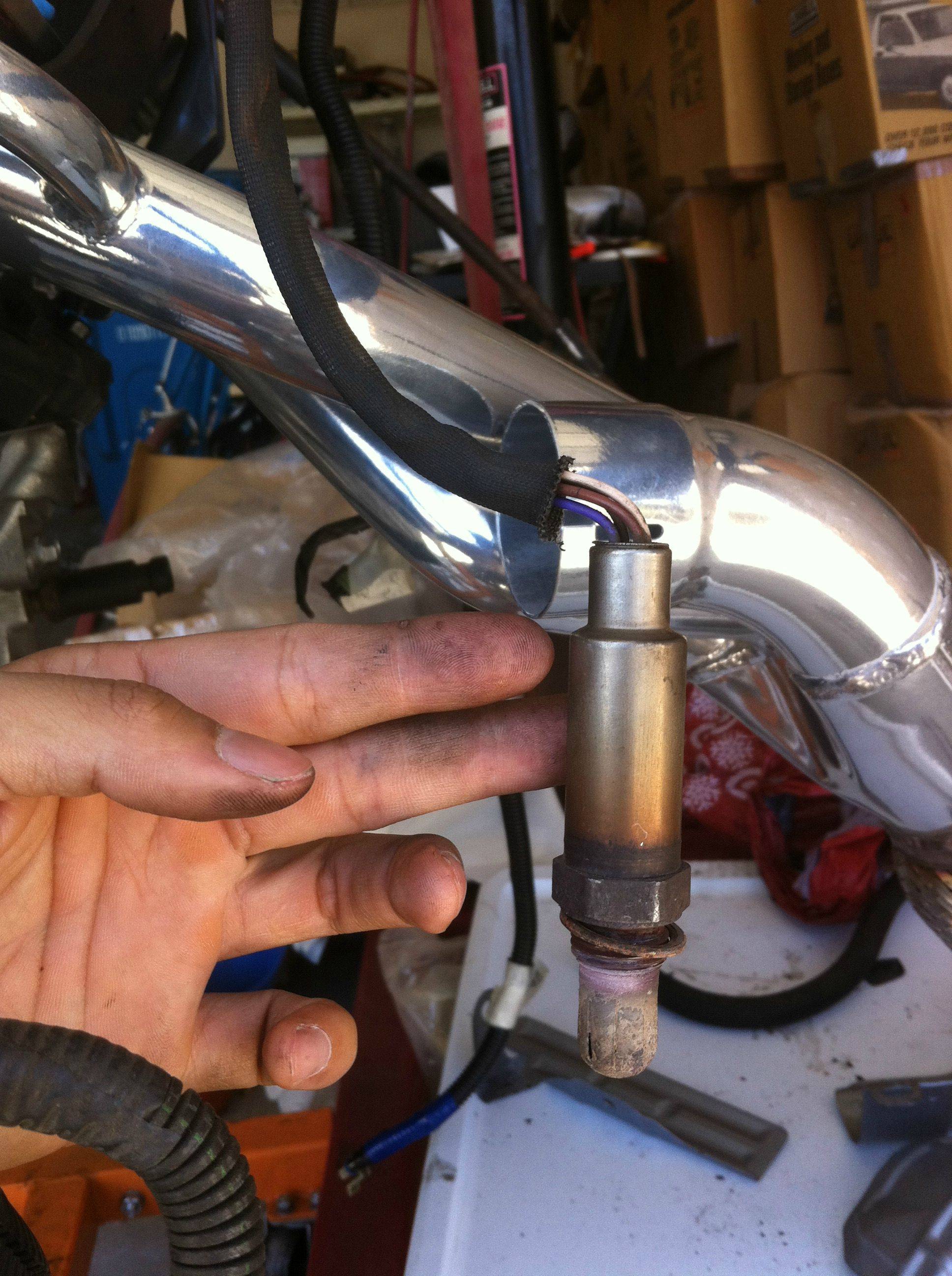
On the subject of the front O2 sensor, would you say this is worth replacing?
Just wanted to clarify, is there another vacuum hose near the passenger side rear like around the accumulator?
So I have another diagram I made up. Are you saying this goes to V3?
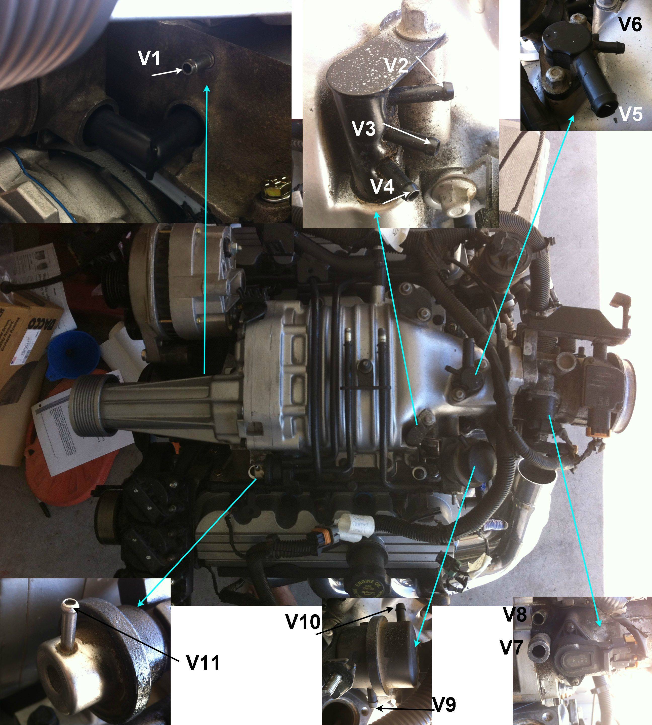
Also, would you (or anyone else) mind identifying where these lines should connect?
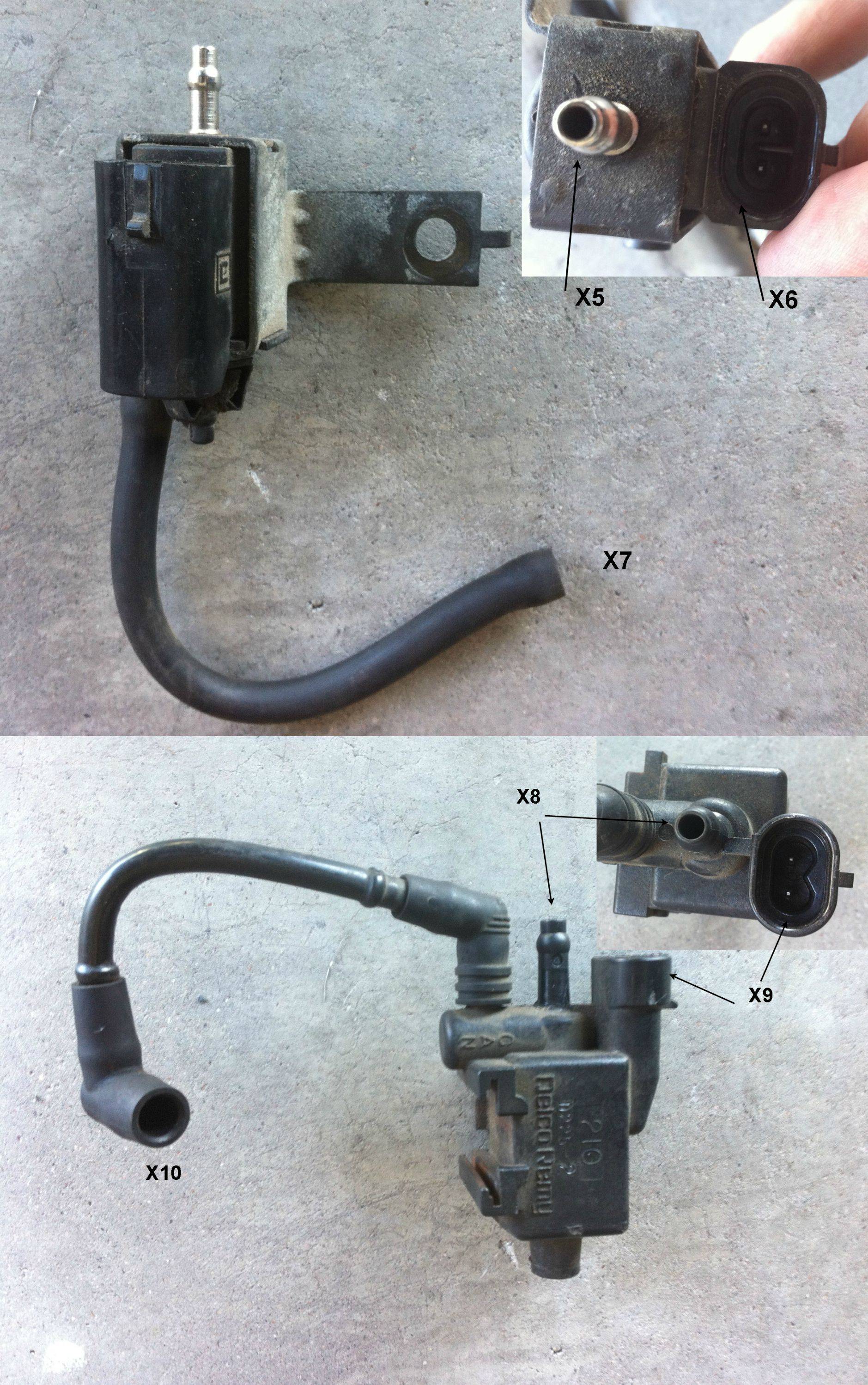
Went ahead and connected the EVAP purge valve (X1) and switch (X9). I found another black box with a metal tube.. is this the one you are talking about? In other words, does X2 connect to X5? Which electrical connection does X6 make? While I still have you where do X7, 8, and 10 go?
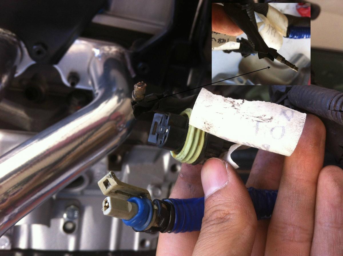
A few other loose ends, in D, I noticed a loose wire. Like it seems to literally be a random wire that sticks out with no real harness. It extends from the same root as the oil pressure sensor and the rear knock sensor (I have the pigtail connected so the orange one is now blue). Any idea what it is?
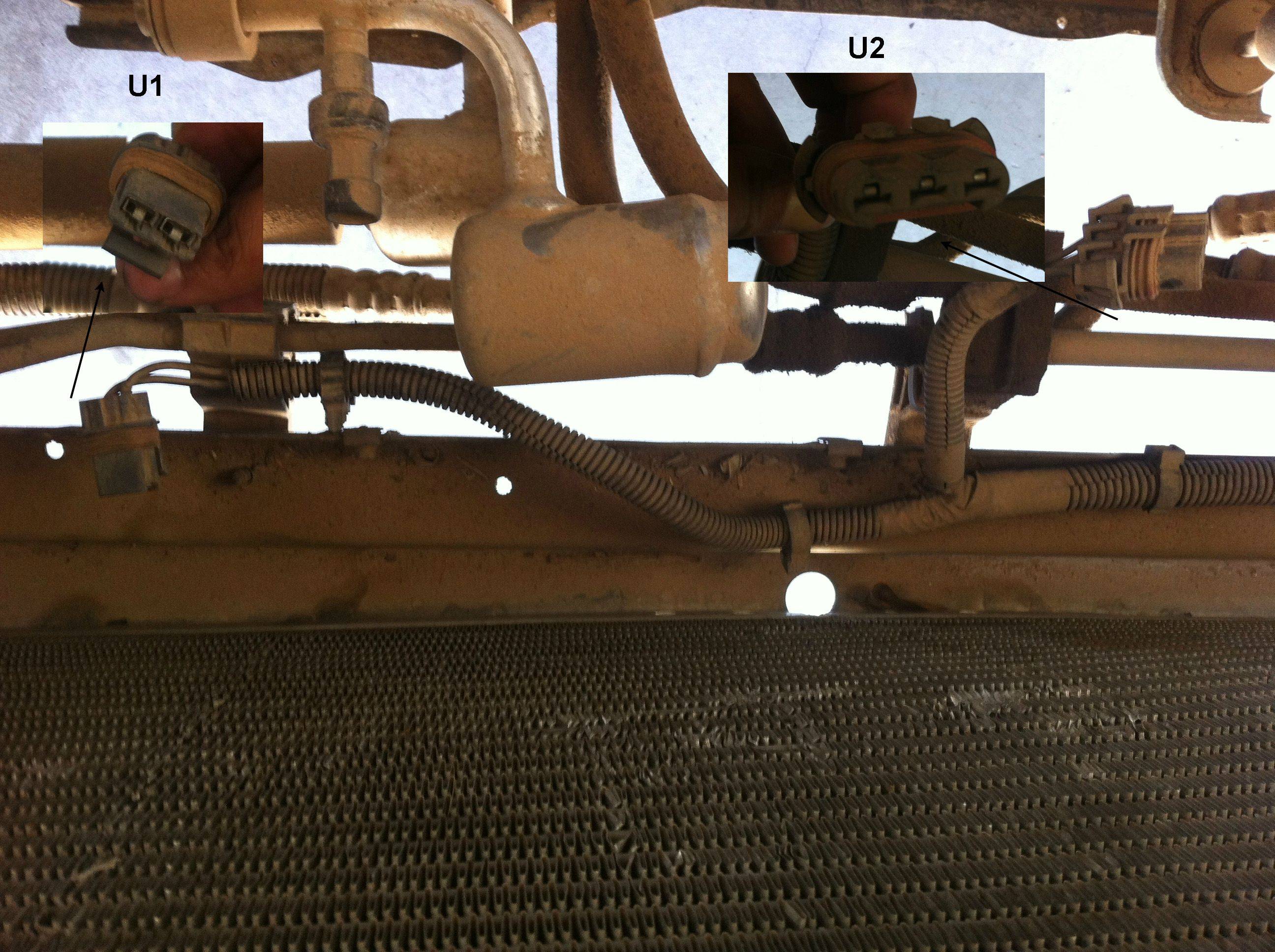
Last but not least, I peaked under the hood and noticed these two guys.. I have a feeling another thread might be coming up with more questions about under the hood stuff....
Originally Posted by BillBoost37
You should have one more F connector for the AC compressor.
Originally Posted by BillBoost37
B3. Looks like a 10 wire, but is in the right place to be EGR. If it'* 5 wires..it'* EGR
Originally Posted by BillBoost37
C1. ICM/Crank/Cam harness (other side typically stays on the motor. Connects right by FPR)
Originally Posted by BillBoost37
B1. Front O2 sensor (96 was a flat connector like this, 97 would have been a square)
Originally Posted by BillBoost37
H1. Other end of B4, it connects to the vac hose you'll find near H
Originally Posted by BillBoost37
B4. Vacuum line (connects to center port on top of SC, is the other end to H1)
Also, would you (or anyone else) mind identifying where these lines should connect?
Originally Posted by BillBoost37
X1. This is the evap purge valve.
You should also have a rectangular black box that would hook to the empty port (not the L hose, the other open port) The rectangle is the evap purge switch.
X2. On the front driverside end of the head, there should be a metal tube bolted up. This hose connects there. if you don't have the tube, run this hose to the evap canister labeled evap.
A few other loose ends, in D, I noticed a loose wire. Like it seems to literally be a random wire that sticks out with no real harness. It extends from the same root as the oil pressure sensor and the rear knock sensor (I have the pigtail connected so the orange one is now blue). Any idea what it is?
Last but not least, I peaked under the hood and noticed these two guys.. I have a feeling another thread might be coming up with more questions about under the hood stuff....
06-24-2012, 12:53 AM
#9
Member
Posts like a V-Tak
Thread Starter
Join Date: Sep 2005
Location: Tempe, AZ
Posts: 73
Likes: 0
Received 0 Likes
on
0 Posts
In another thread, I mention that I am switching out the 4t60E HD that came with my car to a 65E HD. To prepare for this I pulled a 1998 SE N/A wiring harness set and PCM that had the big round green 65E plug.
One thing I noticed on the L36 harness compared to the L67 one that came with my car was that it also had a plug for something on the left of the upper intake manifold. I've posted a picture below (bottom left):
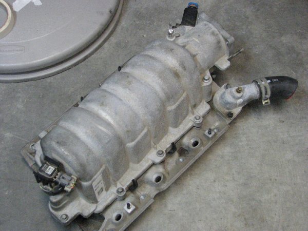
Is this going to cause a problem? Can I still use this wiring harness on the L67?
One thing I noticed on the L36 harness compared to the L67 one that came with my car was that it also had a plug for something on the left of the upper intake manifold. I've posted a picture below (bottom left):
Is this going to cause a problem? Can I still use this wiring harness on the L67?
06-24-2012, 06:39 AM
#10
Retired
Certified Car Nut
On the left corner of the intake plenum is the MAP sensor. On the L67, the MAP sensor is usually located on the backside of the supercharger. With a L36 harness, the 3 wires are not long enough to reach the backside. zzperformance.com has an extension pigtail for the L36 L67 swap. Or, you can just use 3 pieces of wire to extend it.
If your using a L36 harness on the L67, besides the MAP mod I mentioned above, you are going to also have to add 1 wire to the PCM connector for the boost control solenoid, and a 2nd wire for a ground to that solenoid.
Actually, I should have asked specifically to remind us what project your working on. With a swap project like this, we need to know the car this is going into.
__________________
Retired Administrator
2002 *-10 5.7 V8
2023 Jeep Rubicon Diesel
Retired Administrator
2002 *-10 5.7 V8
2023 Jeep Rubicon Diesel

