'98 Bonneville, Instrument cluster issues
#25
Member
Posts like a V-Tak
Thread Starter
Join Date: Dec 2006
Location: Pittsburgh, PA
Posts: 68
Likes: 0
Received 0 Likes
on
0 Posts

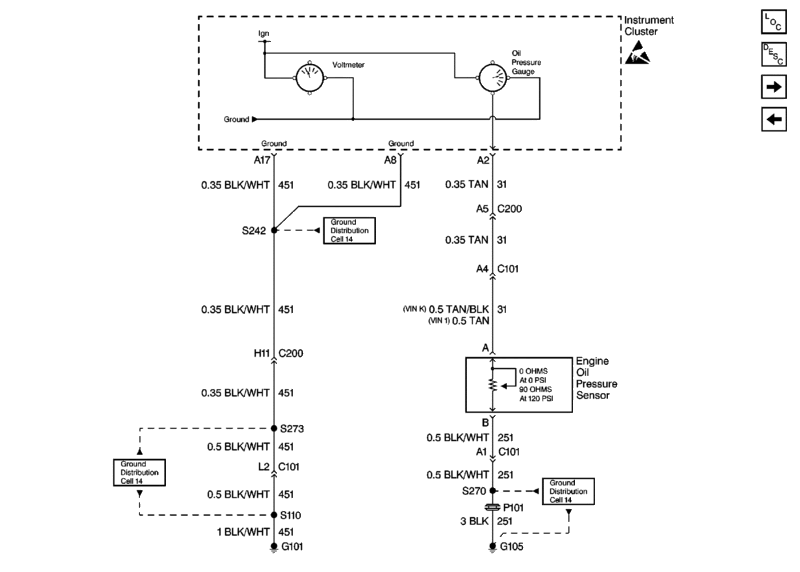
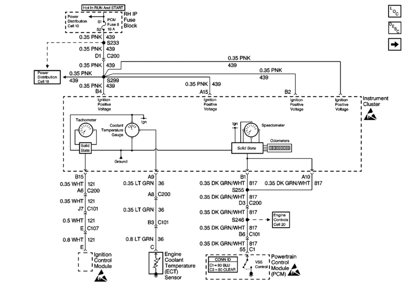
I am working on a strange wiring problem with my Bonneville as some of you already know. The following diagram is for my '98 and I am trying to trace the wiring from the oil pressure gauge to the dash. The diagram shows what I think is the wire number and color but I'm not sure what the termination is. Also I picked another termination on what I think is the dash cluster. I realize that it has nothing to do with the oil pressure sensor, I just want to know what that termination means so that I can continue troubleshooting.
It appears that the oil pressure sensor goes to ground on the fender and then to terminal B1 (whatever that is). The oil pressure sensor in the second drawing is getting data from 2A10, 1B8, and data from 2B1. My oil pressure gauge is whacky as is the check washer fluid light and the check gauges light and I have already changed the gauge cluster. This has to mean that the problem is external to the gauge and the sensor which may mean power or ground to the gauge cluster. If the check gauge lights and check washer fluid lights are freaking out and they are internal to the cluster with no outside wiring, I'm thinking problems with power or ground to the cluster....where ever that comes from....
http://i154.photobucket.com/albums/*...illeWiring.jpg
http://i154.photobucket.com/albums/*...lleWiring2.jpg
#26
Senior Member
Posts like a Turbo
Join Date: Dec 2009
Location: Kitchener On.
Posts: 348
Likes: 0
Received 0 Likes
on
0 Posts

I am working on a strange wiring problem with my Bonneville as some of you already know. The following diagram is for my '98 and I am trying to trace the wiring from the oil pressure gauge to the dash. The diagram shows what I think is the wire number and color but I'm not sure what the termination is. Also I picked another termination on what I think is the dash cluster. I realize that it has nothing to do with the oil pressure sensor, I just want to know what that termination means so that I can continue troubleshooting.
It appears that the oil pressure sensor goes to ground on the fender and then to terminal B1 (whatever that is).
It appears that the oil pressure sensor goes to ground on the fender and then to terminal B1 (whatever that is).
the letter represents the connector # for a particular device
-A for first connector, B for second connector and so on
the number represents the terminal # for that particular connector
-usually starts at 1 at top left of connector (if more than one row of terminals)
#27
DINOSAURUS BOOSTUS

Expert Gearhead
Can't quite see the picture you posted. I went back to the schematic from a day or so ago and here'* how the OP gauge is fed.
G105 is a ground located: Right front of the engine compartment, near the battery
That wire is black with a white tracer and then goes through P101 this is a passthrough grommet located: Right rear of the engine compartment, near the right front strut tower
From there it comes back through the firewall via pin A1 of C101, a large connector located: Body harness to the engine harness, right rear of the engine compartment near the strut tower. This is the main connection for all engine related wiring to the firewall.
The black wire with white tracer continues from C101 to the oil pressure sensor connector. It is in the connector as pin B.
The signal of oil pressure is sent via ohms out of the oil pressure sensor connector at pin A as a Tan wire.
From the oil pressure sensor connector, the tan wire travels to connector C101 on the firewall and is in the cavity labeled Pin A4.
Once back in the cabin on Pin A4 of C101, the wire travels in the main dash wiring harness to the main dashboard connector C200. C200 is located at the middle of the dashboard, about mid height behind the radio. The tan wire is located in C200 at the location for Pin A5.
From there it arrives at the instrument cluster connector into Pin A2, Tan in color.

#28
DINOSAURUS BOOSTUS

Expert Gearhead
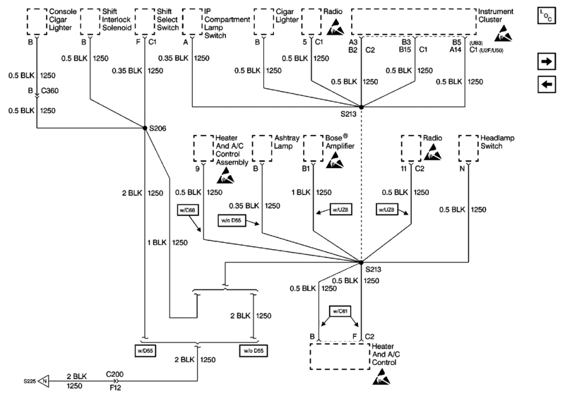
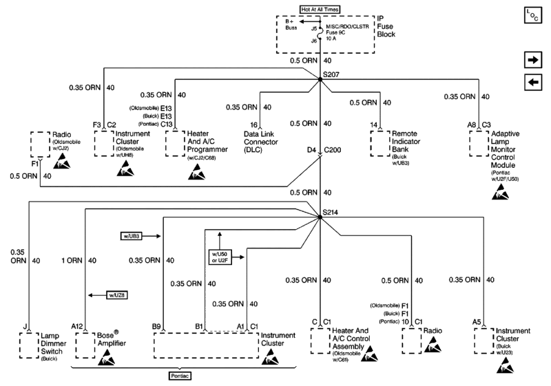
Here'* more on ground and power to the cluster. Although I'm not having an easy time finding the actual pin for each as the cluster has a couple of each.


And if you follow things out to S213 that'* located at number 19 in this picture.


And if you follow things out to S213 that'* located at number 19 in this picture.

#29
Senior Member
Posts like a Turbo
Join Date: Dec 2009
Location: Kitchener On.
Posts: 348
Likes: 0
Received 0 Likes
on
0 Posts

I just fround this test run the test and report an abnormal results, might be good idea as you say more than just OP gauge are whacky
Document ID# 469239
1998 Pontiac Bonneville
Instrument Cluster System Check
<A href="http://127.0.0.1:9001/servlets/BlobShtml?ShtmlFile=469239&pubid=59&evc=sm&cellId= 50851#tab1-469239">Instrument Cluster (IPC) System Check
Step
Action
Normal Result(*)
Abnormal Result(*)*
1
Fasten Safety Belt Indicator Always On
3
Apply the park brake.
The park brake indicator illuminates.
Brake Warning Indicator Inoperative. Refer to Brake Warning System Check in Hydraulic Brakes.
4
Turn the headlights on.
6
Adjust the instrument panel dimmer control.
The IPC illumination varies based on the dimmer control adjustment.
IPC Illumination Does Not Vary. Refer to Interior Lights Dimming System Check in Lighting Systems.
7
Turn the high beam headlamps on.
The high beam indicator illuminates.
Start the engine.
9
Press the IPC control button E/M (Olds w/UH .
.
The measurement units change for the IPC and HVAC displays.
Driver Information Switch Inop - English/Metric
10
Press and hold the IPC control button TRIP for 3 seconds while trip odometer is displayed (Olds w/UH .
.
The trip odometer resets to zero.
Driver Information Switch Inop - Trip Reset
11
Press the IPC control Button TRIP select (Olds w/UH .
.
The IPC toggles between trip odometer and total odometer values.
Driver Information Switch Inop - Trip A/B
12
Observe the fuel gauge.
The fuel gauge indicates the correct fuel level.
Observe the engine temperature gauge.
The engine temperature gauge indicates the correct engine temperature.
Engine Coolant Temp Gauge Inaccurate/Inoperative
14
Observe the tachometer.
The tachometer indicates the correct engine speed.
Tachometer Does Not Operate Properly
15
Observe the Service Engine Soon indicator.
Service Engine Soon indicator is off.
Service Engine Soon Indicator On. Refer to Engine Controls Diagnostic System Check. in Engine Controls.
16
Observe the low engine oil indicator.
The low engine oil indicator is off.
Engine Oil Pressure Indicator Always On
17
Observe the battery charge indicator.
The battery charge indicator is off.
Battery Charge Indicator Always On. Refer to Engine Electrical.
18
Observe the Air Bag indicator.
The Air Bag indicator is off.
Air Bag Indicator On. Refer to SIR Diagnostic System Check in SIR.
19
Observe the ABS indicator.
The ABS indicator is off.
ABS Indicator On. Refer to ABS Diagnostic System Check in ABS.
20
Observe the traction control indicator (if equipped).
The traction control indicator is off.
Traction Control Indicator On. Refer to ABS Diagnostic System Check in ABS.
21
Observe the engine coolant temperature indicator.
The engine coolant temperature indicator off.
Engine Coolant Temperature Indicator Always On
22
Observe the SECURITY indicator.
The SECURITY indicator is off.
Security Indicator On. Refer to Theft Deterrent System PASS Key System Check in Theft Deterrent.
23
Cycle the gear selector lever through all of the gear positions.
25
Turn the hazard flashers on.
Both turn indicators flash.
Hazard flashers inoperative
26
For Pontiac U50/U2F, perform the following steps:
For Pontiac U50/U2F, perform the following steps:
Compass Display Inoperative (IPC)
28
For Pontiac U50/U2F, perform the following steps:
The IP dimming switch does not vary the compass display intensity with the headlights on. Refer to Lighting System Check in Lighting Systems.
29
Document ID# 469239
1998 Pontiac Bonneville
Document ID# 469239
1998 Pontiac Bonneville
Instrument Cluster System Check
<A href="http://127.0.0.1:9001/servlets/BlobShtml?ShtmlFile=469239&pubid=59&evc=sm&cellId= 50851#tab1-469239">Instrument Cluster (IPC) System Check
Step
Action
Normal Result(*)
Abnormal Result(*)*
1
- <LI type=1>Close all of the vehicle'* doors. <LI type=1>Leave the safety belt unbuckled. <LI type=1>Verify the gear selector is in the PARK position.
- Turn the ignition switch to the ON position.
- The vehicle performs a bulb check on the indicators. The following indicators illuminate briefly:
- Driver Information Center
- ABS
- Traction OFF
- Air Bag
- Fasten Belts
- Battery Charge
- Malfunction Indicator (UB3 Pontiac)
- Check Gauges (UB3 Pontiac)
- Engine Coolant Temperature
- Check Oil Level (UB3 Pontiac)
- Engine Oil Pressure
- Compass Display (U50/U2F Pontiac)
- Park Brake
- Security
- The vehicle performs a check on the following gauges (the gauge pointers sweep through the appropriate range):
- Engine Temperature
- Fuel
- Voltmeter (UB3/U50 Pontiac)
- Boost (U2F Pontiac)
- Coolant Temperature
- All of the compass display segments will light for about 3 seconds (U50/U2F Pontiac):
- After 3 seconds, the vehicle heading displays
- For 3 seconds, ZONE and the current zone number display
- All Gauges Inoperative
- Battery Charge Indicator Inoperative in Starter and Charging
- Engine Coolant Temperature Indicator Inoperative
- Engine Oil Pressure Indicator Inoperative.
- Fasten Safety Belt Indicator/Chime Inoperative
- Security Indicator Inoperative. Refer to Theft Deterrent Diagnostic System Check in Theft Deterrent.
- CALIBRATE displays. Refer to Manual Calibration Mode.
- Compass Display Inoperative (IPC)
- <LI type=1>Buckle the driver'* safety belt.
- Observe the fasten safety belt indicator.
Fasten Safety Belt Indicator Always On
3
Apply the park brake.
The park brake indicator illuminates.
Brake Warning Indicator Inoperative. Refer to Brake Warning System Check in Hydraulic Brakes.
4
- Operate the left turn signal.
- Operate the right turn signal.
- Left Turn Indicator Is Inoperative
- Right Turn Indicator Inoperative
- Left Turn Indicator Always On
- Right Turn Indicator Always On
Turn the headlights on.
- The IPC illumination turns on and dims to the setting on the dimmer control.
- The LIGHTS ON indicator illuminates (Buick and Olds w/UH
 .
.
6
Adjust the instrument panel dimmer control.
The IPC illumination varies based on the dimmer control adjustment.
IPC Illumination Does Not Vary. Refer to Interior Lights Dimming System Check in Lighting Systems.
7
Turn the high beam headlamps on.
The high beam indicator illuminates.
- High Beam Indicator Inoperative
- High Beam Indicator Is Always On
Start the engine.
- The engine cranks and starts.
- The speedometer displays zero.
9
Press the IPC control button E/M (Olds w/UH
The measurement units change for the IPC and HVAC displays.
Driver Information Switch Inop - English/Metric
10
Press and hold the IPC control button TRIP for 3 seconds while trip odometer is displayed (Olds w/UH
The trip odometer resets to zero.
Driver Information Switch Inop - Trip Reset
11
Press the IPC control Button TRIP select (Olds w/UH
The IPC toggles between trip odometer and total odometer values.
Driver Information Switch Inop - Trip A/B
12
Observe the fuel gauge.
The fuel gauge indicates the correct fuel level.
- Fuel Gauge Inaccurate or Inoperative
- Fuel Gauge Always Indicates Empty
- Fuel Gauge Always Indicates Full
Observe the engine temperature gauge.
The engine temperature gauge indicates the correct engine temperature.
Engine Coolant Temp Gauge Inaccurate/Inoperative
14
Observe the tachometer.
The tachometer indicates the correct engine speed.
Tachometer Does Not Operate Properly
15
Observe the Service Engine Soon indicator.
Service Engine Soon indicator is off.
Service Engine Soon Indicator On. Refer to Engine Controls Diagnostic System Check. in Engine Controls.
16
Observe the low engine oil indicator.
The low engine oil indicator is off.
Engine Oil Pressure Indicator Always On
17
Observe the battery charge indicator.
The battery charge indicator is off.
Battery Charge Indicator Always On. Refer to Engine Electrical.
18
Observe the Air Bag indicator.
The Air Bag indicator is off.
Air Bag Indicator On. Refer to SIR Diagnostic System Check in SIR.
19
Observe the ABS indicator.
The ABS indicator is off.
ABS Indicator On. Refer to ABS Diagnostic System Check in ABS.
20
Observe the traction control indicator (if equipped).
The traction control indicator is off.
Traction Control Indicator On. Refer to ABS Diagnostic System Check in ABS.
21
Observe the engine coolant temperature indicator.
The engine coolant temperature indicator off.
Engine Coolant Temperature Indicator Always On
22
Observe the SECURITY indicator.
The SECURITY indicator is off.
Security Indicator On. Refer to Theft Deterrent System PASS Key System Check in Theft Deterrent.
23
Cycle the gear selector lever through all of the gear positions.
- The PRNDL displays the correct gear positions.
- The park brake indicator turns off.
- PRNDL Indicator Inoperative
- Brake Warning Indicator Always On. Refer to Brake Warning System Check in Hydraulic Brakes.
- <LI type=1>Drive vehicle at 48 km/h (30 mph). <LI type=1>Ensure that the cruise switch is ON (Buick only).
- Push the SET CRUISE button (Buick only).
- The speedometer and the odometer operate properly.
- Cruise indicator illuminates (Buick only).
25
Turn the hazard flashers on.
Both turn indicators flash.
Hazard flashers inoperative
26
For Pontiac U50/U2F, perform the following steps:
- <LI type=1>Turn the rear defogger OFF. <LI type=1>Drive the vehicle to a flat area. Ensure that the area is at least 15 m (50 ft) from buildings and other cars. <LI type=1>Verify that you are using the correct zone number.
- Drive the vehicle in the following directions:
- North
- South
- East
- West
- The correct zone number displays.
- The compass display shows the correct vehicle heading.
- The incorrect zone number displays. Refer to Variation Mode.
- Compass Display Inoperative (IPC)
For Pontiac U50/U2F, perform the following steps:
- <LI type=1>Turn the rear defogger ON.
- Drive the vehicle in the following directions:
- North
- South
- East
- West
Compass Display Inoperative (IPC)
28
For Pontiac U50/U2F, perform the following steps:
- <LI type=1>Turn the headlights ON.
- Use the IP dimming switch in order to vary the intensity of the compass display.
The IP dimming switch does not vary the compass display intensity with the headlights on. Refer to Lighting System Check in Lighting Systems.
29
- <LI type=1>Turn the ignition switch to RUN. <LI type=1>Operate all of the exterior lights.
- Inspect the driver information center (DIC) for a bulb outage.
- Driver Information Center (DIC) Does Not Display Bulb Outages or Displays LAMP MONITOR PROB
- Driver Information Center (DIC Working Properly, but Does Not Display a Specific Bulb Outage
Document ID# 469239
1998 Pontiac Bonneville
Thread
Thread Starter
Forum
Replies
Last Post
jaye22
Everything Electrical & Electronic
1
04-15-2010 04:14 PM


