1963 Pontiac Catalina massive project build thread
 01-27-2013, 05:29 PM
#121
Senior Member
Posts like a Turbo
Thread Starter

I had not realized how long it'* been since I posted. It'* been a while since I got the motor home. I've been getting parts again and doing little things. Yesterday I threw off the gloves and took the monster on. I trimmed, fitted, and siliconed the crank scraper down. I found that the bolt heads on the Hilborn pump drive bolts were too big and were hitting inside the Moon pump mounting cover. I had to go on a hunt to find proper bolts but ended up getting some button head bolts, and grinding down the circumefrence enough to get the bolt head to fit in the pump drive slots. All good now. Installed the front cover and pressed on the front ATI balancer. The Moon cover with the added thickness of the pump drive cover, is just too thick to allow the balancer to bottom out on the bottom timing chain gear. ATI sells crankshaft shims/spacers so I'll be calling them tomorrow. Since all my pulleys will be custom installed I don't care where the bottom pulley ends up. I bought a Precision Pumps blueprinted 80 lb pump too. So that went on with the pickup for my oil pan. Last night I shot a coat of paint of the engine and the oil pan. But when I tried to install the pan, it'* hitting on something inside preventing it from dropping down in place. I'll have to figure that out. Previously I had painted the Moon cover leaving the machined tops of ribs polished, and I painted between the ribs on the blower scoop too. I have not had time to do a good cleaning of the ribbed valve covers but they will get painted between the ribs eventually too. So I mocked up the painted motor to take some preliminary pics.
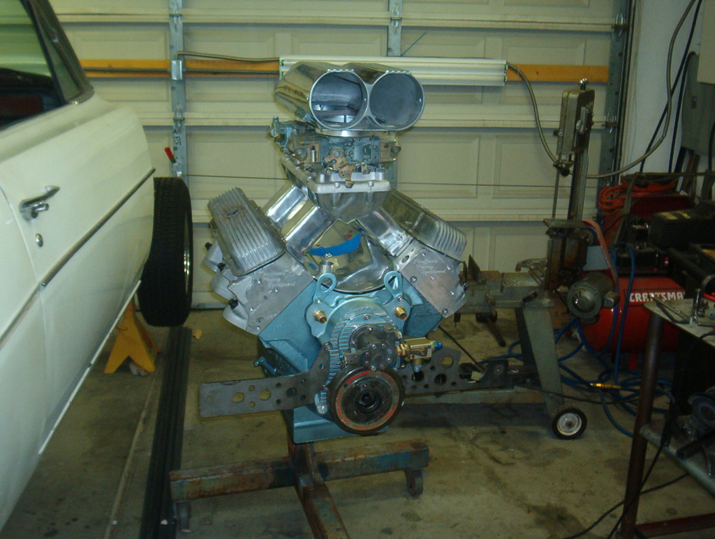

Got much to do yet. Once I get the oil pan figured out and installed I will place the motor up on the steel table and start all the mods to get a starter bolted on. I was doing a lot of stuff while I still had the '59 block I had found. But I really needed the actual block that I was using so I could finalize every mod as I went along. Now I can do that and "I have a plan", heh. So far so good.
Mark L
 01-31-2013, 09:02 PM
#123
Senior Member
Posts like a Turbo
Thread Starter
More updates. I was having clearance problems with my ATi Balancer and the Moon front cover. The added thickness of the Hilborn pump mount plate on the front cover caused the balancer to hit and prevent me from drawing the the balancer all the way down. I ground everything I could on the timing cover and the plate. I finally got enough clearance that I got the balancer all the way down and bottomed out. But the top of the balancer was so close to everything up there that I was afraid if the balancer did not run perfectly true, it would be hitting. Then, when I tried to torque the balancer down I realized that the crank should have started moving under the torque that I was putting to the bolt. That'* when I realized the bottom of the front cover oil pan flange was tight against the balancer. ATi sells crank spacers so I just went and ordered two .093 spacers and it'll be done. Plus it will give me back some clearence at the top of the balancer. I'll feel better with that.
Next I had to get the motor to Top Dead Center. But the heads were already installed. I tried to find a way to create a piston stop from the bottom of the motor but it was just to hard to do. So I removed the head. I used an old piston stop I made years ago and a degree wheel and got my TDC. I marked the front cover at the TDC location, drilled and tapped the timing cover for a 10-24 machine bolt, ground a point on it and added a nut. Screwed it into the cover and locked it in. The balancer is just sitting on the end of the crank, that'* why it is not up against the cover in the pic.

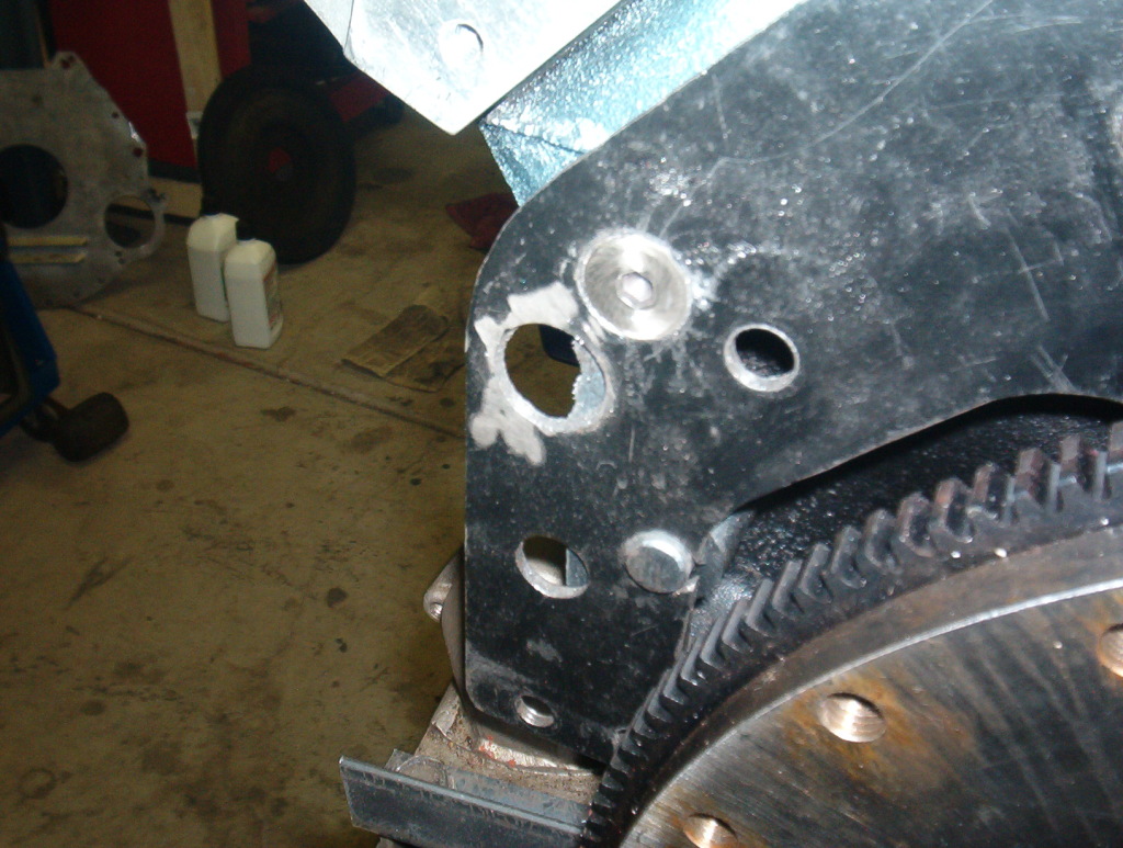
This is a close up shot of how I'm going to mount the later starter. The early blocks do not have enough of the block flange stickng out to add the outside starter bolt. So I've add an angle iron extension. I located the starter properly for engagement. Then drilled the inside bolt hole and tapped it thru the angle iron into the block flange. The angle iron goes outside of the first adaptor plate that you can see just the edge of in the pic. The outside bolt goes thru a hole and will get a nut welded on the top so both starter bolts can be put in from the bottom. Then the angle iron piece will get welded to the first plate.

More on the starter and adaptor plates next. Mark L
Next I had to get the motor to Top Dead Center. But the heads were already installed. I tried to find a way to create a piston stop from the bottom of the motor but it was just to hard to do. So I removed the head. I used an old piston stop I made years ago and a degree wheel and got my TDC. I marked the front cover at the TDC location, drilled and tapped the timing cover for a 10-24 machine bolt, ground a point on it and added a nut. Screwed it into the cover and locked it in. The balancer is just sitting on the end of the crank, that'* why it is not up against the cover in the pic.
This is a close up shot of how I'm going to mount the later starter. The early blocks do not have enough of the block flange stickng out to add the outside starter bolt. So I've add an angle iron extension. I located the starter properly for engagement. Then drilled the inside bolt hole and tapped it thru the angle iron into the block flange. The angle iron goes outside of the first adaptor plate that you can see just the edge of in the pic. The outside bolt goes thru a hole and will get a nut welded on the top so both starter bolts can be put in from the bottom. Then the angle iron piece will get welded to the first plate.
More on the starter and adaptor plates next. Mark L
01-31-2013, 09:17 PM
#124
Senior Member
Posts like a Turbo
Thread Starter
I'm using two plates for adaptors. One is a Chevy to BOP adaptor and the second is an AllPontiac motor plate. Both plates came drilled for the Chevy and BOP patterns. I added the early Pontiac pattern to them. This is the first adaptor on the block with the two ground down flat head bolts. The starter angle iron adaptor goes up against the bottom of the block flange and sticks up behind the first trans adaptor. The second plate/motor plate face will go level with the angle iron. The second plate will get cut out so the block saver plate for the blowproof bellhousing lays flat over the second plate and the angle iron.

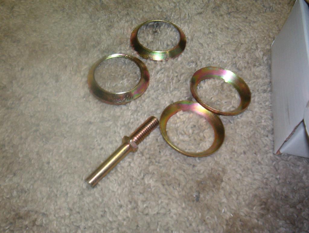
A pic of the ground down flat head bolt. You can also see the extra holes for adapting the various patterns.
This is the starter in place with the angle iron plate to be attached to the block and plates.

This is the second/motor plate in place.
This is the starter again but with the motor plate in place. Once the starter angle iron is located and bolted in, the motorplate will get cut around it so the plate and the starter angle iron is level.

MArk L
A pic of the ground down flat head bolt. You can also see the extra holes for adapting the various patterns.
This is the starter in place with the angle iron plate to be attached to the block and plates.
This is the second/motor plate in place.
This is the starter again but with the motor plate in place. Once the starter angle iron is located and bolted in, the motorplate will get cut around it so the plate and the starter angle iron is level.
MArk L
02-13-2013, 08:43 PM
#125
Senior Member
Posts like a Turbo
Thread Starter
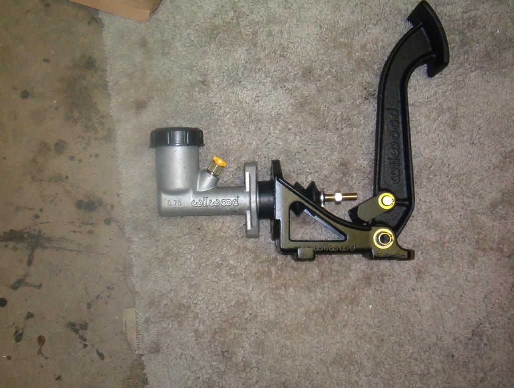
I decided to go with a hydraulic throw out bearing. So I got the Speedway hydraulic throw out, Wildwood 3/4 bore master (required for the bearing) and the floor mounted Wildwood pedal assembly. You assemble the complete clutch bellhousing but do not install the trans. Take a straight edge to lay across the face of the bellhousing (trans mounting face) and measure from the flat of the mounting face to the clutch fingers (where the throwout bearing contacts the clutch fingers). My measurement was 2 3/4 inches. Then you take the hydraulic throw out bearing assembly and slide it onto the trans throwout collar. All the way back. Measure the front contact face of the throwout bearing back to the trans mounting face. On mine it came to just a hair under 2 1/2 inches. So I had to shim the bearing assembly out. They give you several shims to use, all are .050 thick. I used 3 shims and it came out almost exactly at to 2 3/4 inches. The throwout assembly has two fittings that come out the side of the bearing. They give you two threaded studs to replace one of the trans bearing retainer bolts at the two o'clock position. The stud, once mounted, goes between the two fittings to prevent the bearing from spinning. One fitting is the fluid source from the master cylinder, the other is a bleeder valve. I still have to get everything kind of mocked up so I know how long of a braided line to buy to connect the two. These are the pics.
The new hydraulic bearing assembly slid on the trans collar. You can also see the locating stud and the fittings on the bearing in the next two pics.

The bearing slid forward to expose the shims I used.

These are the extra shims and the other stud that I did not use. They give you two sizes for different trans.
This is the pedal and the master assembly.
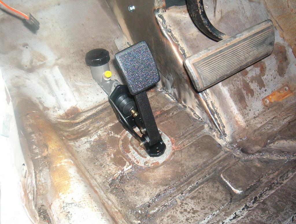
And this is where it will go. I have to remove the brake pedal and cut it down to a normal stick pedal size. This will allow me to move the clutch pedal assembly over closer to the brake. I'll also have to reinforce the floor where the pedal mounts because it is pretty flimsy right there.
When you meet those measurements using the shims etc, it says you should have .050 clearance between the bearing face and the fingers. I won't know until I get my braided line an dinstall it. Then I can slip it all together.
Mark L
The new hydraulic bearing assembly slid on the trans collar. You can also see the locating stud and the fittings on the bearing in the next two pics.
The bearing slid forward to expose the shims I used.
These are the extra shims and the other stud that I did not use. They give you two sizes for different trans.
This is the pedal and the master assembly.
And this is where it will go. I have to remove the brake pedal and cut it down to a normal stick pedal size. This will allow me to move the clutch pedal assembly over closer to the brake. I'll also have to reinforce the floor where the pedal mounts because it is pretty flimsy right there.
When you meet those measurements using the shims etc, it says you should have .050 clearance between the bearing face and the fingers. I won't know until I get my braided line an dinstall it. Then I can slip it all together.
Mark L
02-13-2013, 08:49 PM
#126
Senior Member
Posts like a Turbo
Thread Starter
I also finished setting my valves today. My cam has the 4/7 swap. But I thought when the 4/7 swap is made generally the 5/3 is swapped too. I started following the LS1 firing order but the second half of the order did not follow the LS1 order. Unless I'm crazy or I did something wrong, the cam was cut with only the 4 and 7 cylinders swapped. The 3/5 is the same as the regular Pontiac firing order??? The cam was a special custom ordered cam combination. So I sent an e-mail to the gentleman that built my motor to call the designer/grinder to get the proper firing order. We'll see what happens ther. But I'm very sure that I got the firing order figured out and all is set, ready for start up.
Update. I did talk to Paul Carter about my cam, he said they had designed it with only the 7/4 swap, so I was right after setting the valves. At least I know now.
MArk L
Update. I did talk to Paul Carter about my cam, he said they had designed it with only the 7/4 swap, so I was right after setting the valves. At least I know now.
MArk L
 02-14-2013, 11:28 AM
#128
Senior Member
Posts like a Turbo
Thread Starter
The swap does not afford a sizable (if any real) power increase. It may in a really higher powered combination, lets say 1000 and above. But more importantly, it helps smooth out the engine harmonics and it'* supposed to take some of the stress off of the front of the block. The rear of the block has much more casting material, even gets a "girdle" type affect from the bellhousing "porch" casting. The front is a wide expanse of a flat machined casting that is more prone to split. Plus most blocks will usually stay a 2 bolt cap even when many go to 4 bolts in the center. The larger reinforced rear cap adds to the stabilization and strength back there. MArk L
02-19-2013, 10:05 PM
#129
Senior Member
Posts like a Turbo
Thread Starter
I did preliminary fitting of the tranmission with everything installed. All the adaptors, the bellhousing and the clutch etc. A HEADSUP on the hydraulic throw up bearing. I thought I'd be able to slide the bearing assembly onto the trans input and then slide the whole thing in just taking care to run the hydraulic hoses out of the clutch fork opening. I ran two hoses instead of the single hose. The one hose was normal, the one that brings the hydraulic fluid from the master cylinder. The bearing has a second coupler with a bleed screw like on a caliper. I saw no way to get at the bleed screw once it was inside of the bellhousing the way they showed in the instructions. It would have been way up inside the bellhousing and I would think impossible to get at, especially once in the car. So bought two AN -4 hose lines, one for the hydraulic in and I installed a second -4 AN high pressure line to that bleed fitting running it out of the bellhousing too. I'll run the bleed line up the firewall and make a small bracket to hold it there. Then I can bleed the bearing from the engine compartment. So back to the install. Because of the length of the fittings for the line hoses, you can't fit the bearing plus the fittings, plus the lines all in through the bellhousing trans hole. So you have to place the bearing assembly inside of the bellhousing and install the trans while guiding the bearing onto the bearing collar. Sounds easy but the bearing has an o ring that helps seal it againts the collar. The bearing has to be slid onto the collar through the fork hole with basically just your finger tips. Mine were just not strong enough to push it on but I was able to use a bent small pry bar and large blade screw driver to get in and push the bearing back onto the collar.
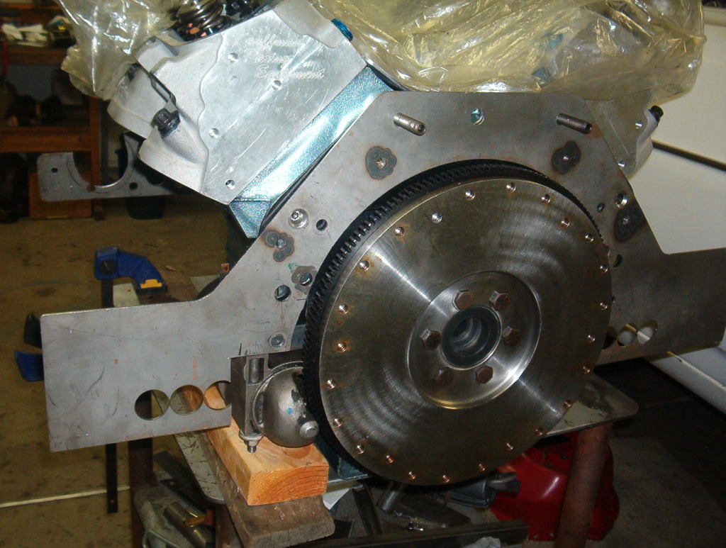
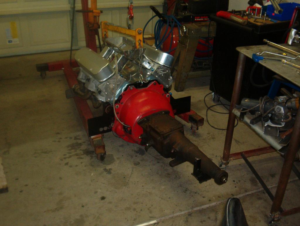
So, BODDA BING, BODDA BOOM, I was able to get it all put in together and bolted down. Then I realized that, although I thought I had done a great job measuring the bearing for clearance using the supplied shims, the bearing was up right against the clutch fingers. I could just move the bearing but it was touching against the fingers. The installation instructions said the mesurements should leave you with about .050 clearence when all the measuring is done. Each shim was .050 thick so I had to pull the trans, pull one shim, and do the install all over again. This is a pic of the assembled engine and tranmission:
This is a pic I finally got from the BOP Fall Festival. It'* me getting the award for Best Special Interest car of all the BOP cars there. That'* Jim Wangers taking the pic with me. He is an Icon in the Pontiac World. Well into his 80'* he is at almost all the POntiac events.

MArk L
So, BODDA BING, BODDA BOOM, I was able to get it all put in together and bolted down. Then I realized that, although I thought I had done a great job measuring the bearing for clearance using the supplied shims, the bearing was up right against the clutch fingers. I could just move the bearing but it was touching against the fingers. The installation instructions said the mesurements should leave you with about .050 clearence when all the measuring is done. Each shim was .050 thick so I had to pull the trans, pull one shim, and do the install all over again. This is a pic of the assembled engine and tranmission:
This is a pic I finally got from the BOP Fall Festival. It'* me getting the award for Best Special Interest car of all the BOP cars there. That'* Jim Wangers taking the pic with me. He is an Icon in the Pontiac World. Well into his 80'* he is at almost all the POntiac events.
MArk L
02-22-2013, 02:29 AM
#130
Senior Member
Posts like a Turbo
Thread Starter
Well I dropped the power plant in it'* final resting place today. Then threw on the carbs and the scoop. It sets perfectly up into the cowl. I have to make the rear motor plate framerail mounts now. This is the motor all installed with the pipes inserted into the shotgun scoop. Somewhat the way they will be.

I cut and fit a front crossmember today to carry the radiator. I've finally given up on installing it in the trunk. You can see the crossmember setting between the framerails inthat previous picture. I have to heat and mould a small depression in the crossmember to clear the steering shaft/coupler, clean the paint off of the frame, and then weld it in. This is the radiator in it'* new location.

I've given up installing it in the trunk. It causes too many problems with making it work. Mounting it back there, getting good air flow to and away from it, and all the piping to move the coolant to and from the front of the car. Not to mention having a big enough water pump to move all that water against the G-force during acceleration contests. The cost of a good strong pump alone makes it something to forget about. I'll get an electric BBChevy pump and mount it up above or below the front mounted fuel pump. Then use hose to run the water from the pump to the block.
I also got the first set of plates welded into the shotgun scoop.

The first set will get gaskets, and I'll drill and tap them for bolts. This is the second set of plates.

These will get welded to the pipes that come from the intercoolers and aligned bolt holes in them to match the first ones in the scoop. The pipes from the intercoolers will go thru these second plates, get welded to the pipes in a correct orientation to match up with the intercoolers. The pipes will go thru the first plates in the scoop into the scoop cavity, and the first and second plates will all be bolted together.
I installed the V-Gate shifter so I can start building my shifter porch. It now falls into a pretty good location.

I started mapping out the front brake lines and line lock etc to get that all together. Speedway sells a nice 18 circuit wiring harness so that may get on the list too. It would be nice ot get the wiring all in.
I'm starting get more stuff done now. It'* a great feeling. Mark L
I cut and fit a front crossmember today to carry the radiator. I've finally given up on installing it in the trunk. You can see the crossmember setting between the framerails inthat previous picture. I have to heat and mould a small depression in the crossmember to clear the steering shaft/coupler, clean the paint off of the frame, and then weld it in. This is the radiator in it'* new location.
I've given up installing it in the trunk. It causes too many problems with making it work. Mounting it back there, getting good air flow to and away from it, and all the piping to move the coolant to and from the front of the car. Not to mention having a big enough water pump to move all that water against the G-force during acceleration contests. The cost of a good strong pump alone makes it something to forget about. I'll get an electric BBChevy pump and mount it up above or below the front mounted fuel pump. Then use hose to run the water from the pump to the block.
I also got the first set of plates welded into the shotgun scoop.
The first set will get gaskets, and I'll drill and tap them for bolts. This is the second set of plates.
These will get welded to the pipes that come from the intercoolers and aligned bolt holes in them to match the first ones in the scoop. The pipes from the intercoolers will go thru these second plates, get welded to the pipes in a correct orientation to match up with the intercoolers. The pipes will go thru the first plates in the scoop into the scoop cavity, and the first and second plates will all be bolted together.
I installed the V-Gate shifter so I can start building my shifter porch. It now falls into a pretty good location.
I started mapping out the front brake lines and line lock etc to get that all together. Speedway sells a nice 18 circuit wiring harness so that may get on the list too. It would be nice ot get the wiring all in.
I'm starting get more stuff done now. It'* a great feeling. Mark L