How to: Megasquirt2 v3.0 and Megatune
 02-07-2011, 08:52 AM
#1
Senior Member
True Car Nut
Thread Starter

Join Date: Jul 2010
Location: Danville, Illinois
Posts: 2,469
Likes: 0
Received 0 Likes
on
0 Posts

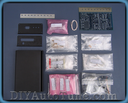
Planning
First step is to plan and buy your megasquirt. I used a v3.0 board and a MS2 processor. http://www.diyautotune.com
Currently, the latest board release is v3.57 and processor is MS3. However, you do not need a v3.57 board to install a MS3 processor. It will work for either board version.
I recommend a V3.0 board because it currently has the best documentation. However, the 3.57 board is pre-assembled if you are not handy with a soldering iron. If you choose a 3.57 board, you need to know this information to use this write-up.

$430 - V3.57 with MS2
$253 - V3.0 no processor included
Processor choice is completely up to you.
The MS2 processor has the best documentation and is easy to set up and use. However, it only has a limited number of inputs and outputs and cannot handle advanced engine operations like sequential fuel injection.
$96
The MS3 processor is very new and much more advanced. It is highly expandable and is for a true enthusiast.

$199 This article however, only covers the MS2 processor.
If you plan on using an electronic transmission, you need to buy and build the GPIO and then install the components for MegaShift. This article is written for a non-electric trans with Torque Converter Clutch.

$235 plus $26 for the Megashift components.
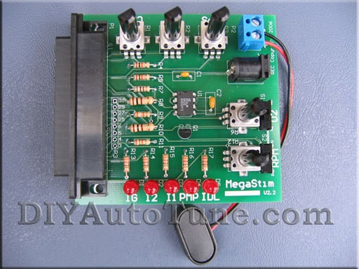
You can optionally buy the Megastim. The stimulator acts as a 'digital car' and is used for assembly/testing/flashing purposes. I highly recommend you buy/build one. It can be good practice if you haven't used a soldering iron in a while.
$45
Assembly
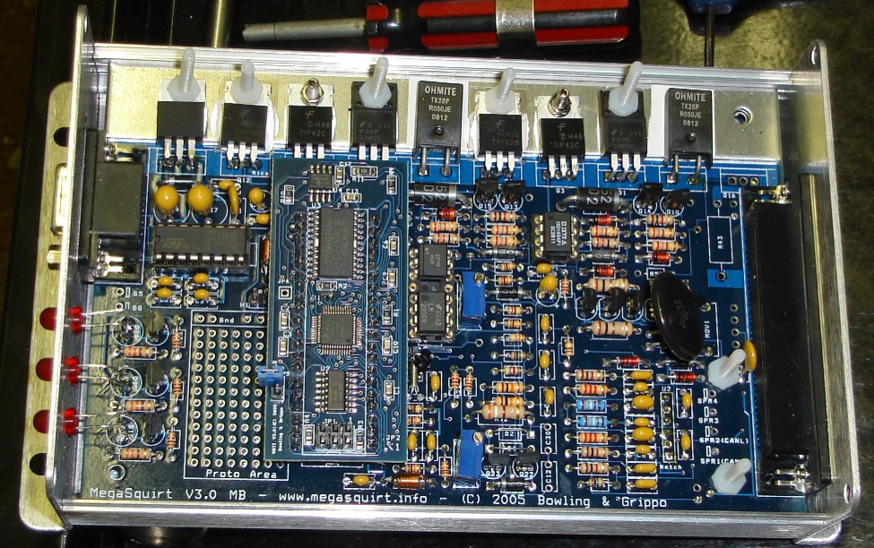
A lot of the information in this write-up is word for word from Megamanuals V3 assembly guide. But I'll just use the information that'* relevant to GM V6s.
You will be referencing this image a lot to identify locations of the components as you are installing them. I recommend you print it.
Power circuit
Install and solder the male DB-37 header (P2) {A23289-ND or A32103-ND} on the PCB. The connectors require a bit of force to 'snap' them into place. Solder all of the pins to give the headers the maximum physical strength. Then install and solder the female DB-9 header (P1) {A23305-ND or A32119-ND}.
Next, install the 40-pin DIP socket {AE7240-ND or AE10018-ND} for the processor - notice that the notch installs near the bottom of the board, corresponding to the PCB silk screen. The socket must be installed from the top of the board, and soldered from the bottom side. To prevent the socket from falling out while you turn the board upside down and solder, you can use a bit of scotch tape across the socket to hold it in place (this works for many of the ICs and some other components). Carefully solder the socket, and inspect each solder joint for shorts (to adjacent pins) or cold joints (solder applied to a joint the isn't hot enough to flow properly, typically they won't have a nice 'cone' to the solder).
Next, you are going to install the components that make up the power supply, and then verify operation. The first part to install is the 'Perry' Metal Oxide Varistor MOV1 {P7315-ND}. This is a large flat disc, about an inch (~25mm) in diameter. It is soldered near the DB37 connector, and does not have a polarity, it can go either way around. This part protects the MegaSquirt� from surges on the 12 volt line.
Install the capacitor C15 {399-4202-ND, 0.001 �F, 102 marking}. This goes near the MOV1 you just installed, between it and "Grippo" in the copyright notice.
Install and solder C16 {399-1420-ND or 399-3584-ND, a tantalum capacitor, 22 microFarads (�F), 226 marking} - make sure polarity is observed. It has a small “+” near the positive lead. The longer lead is also always the positive lead. It is located next to the DB9 connector.
Install and solder C17 {399-1420-ND or 399-3584-ND, tantalum, 22 �F} - make sure polarity is observed. The longer lead is positive on all of the capacitors. It is located next to the C16 capacitor you just installed, near the DB9 connector.
Install and solder C18 {399-4329-ND, 0.1 �F, 104 marking}. This installs near the DB9 connector, just above (closer to the heat sink area) the C17 capacitor you installed in the last step.
Install and solder C19 {399-4329-ND, 0.1 �F capacitor, 104 marking}. This installs near the CPU #1 pin.
Install and solder C23 {399-4329-ND, 0.1 �F capacitor}. This installs near CPU pin #21.
Install and solder C22 {399-3559-ND, 4.7 �F electrolytic} - make sure polarity is observed. It is located very close to C23.
Install and solder D9 {1N4001DICT-ND} - make sure banded end is installed correctly as per board. This installs near the DB9 connector, very near U5 on the heat sink. To do this, make sure the end of the diode with the band on it goes to the end of the silkscreen (at D9) that has the band nearest it.
Install and solder D10 {1N4001DICT-ND} - make sure banded end is installed correctly as per board. This is installed near the MOV1 you installed earlier.
Install and solder diode D11 {1N4001DICT-ND} - make sure banded end is installed correctly as per board. This is installed near the MOV1 you installed earlier.
Install and solder D12 {1N4749ADICT-ND, 24 volt Zener} - make sure banded end is installed correctly as shown on the printed circuit board. This installs very near D10 and D11.
Install and solder diode D13 {1N4742ADICT-ND, 12 volt Zener, 1N4742 marking} - make sure banded end is installed correctly as per the board. It is located above the column of capacitors above "Grippo" in the copyright notice.
Install and solder diode D19 {1N4734ADICT-ND, 5.6 volt Zener, 1N4734 marking} - make sure banded end is installed correctly as per the board. It is located in the upper right section of the board (near the DB37 and heat sink), below the Q14 and Q10 transistor and R32, R30 & R31 resistors.
Install and solder L1 {M8388-ND, inductor, 1�H, small coil of wire with leads}. It is installed near the notched end of the CPU socket. Space the inductor about 1/8” (3mm) off the PCB to avoid shorts on the traces underneath.
Install and solder L2 {M8388-ND, inductor, 1�H}. It is installed between the CPU socket and the DB9 connector. Space the inductor about 1/8” (3mm) off the PCB to avoid shorts on the traces underneath.
Install and solder F1 and F2 {RXEF050-ND}. These are � Amp poly fuses (small yellow discs that look similar to some capacitors) that acts like a circuit breaker on the 5 Volt supply to the PCB from the regulator. F1 installs very near the DB9, in the middle of some of the capacitors you have already installed. F2 installs near the center of the DB37 connector, and very close to it.
Install the voltage regulator U5 {LM2937ET-5.0-ND}. This part installs near the DB9 connector on the top of the board. Use heat-sink compound on the tab, and use the nylon screw and nut to fasten to the PCB. The leads go through the board and are soldered on the top side.
Install a jumper from the hole marked S12C to the hole marked JS9 (+12C). These are on the bottom side of the board, on the DB9 side of the processor.
Connect the following jumper wires to control your GM IAC valve:
* Connect (1A)JS0 (under the processor socket) to IAC1A (near the DB37 connector) - this brings out IAC1A on DB37 pin #25
* Connect (1B)JS1 (under the processor socket) to IAC1B (near the DB37 connector) - this brings out IAC1B on DB37 pin #27
* Connect (2A)JS2 (under the processor socket) to IAC2A (near the DB37 connector) - this brings out IAC2A on DB37 pin #29
* Connect (2B)JS3 (under the processor socket) to IAC2B (near the DB37 connector) - this brings out IAC2B on DB37 pin #31
Since we will be using an ignition output signal to control an ignition module with MS-II, jumper JS10 to IGBTIN, then jumper IGBTOUT to IGN. JS10 is on the bottom side of the board under the processor slot.
If you want to use CAN communications (if you plan on using an electronic trans and plan on building a GPIO board to control it), jumper JS6 to SPR1/CANH and JS8 to SPR2/CANL
Testing the power circuit is important to make sure you built everything correctly. Directions for testing can be found on the megamanual V3.0 assembly instructions - Step 23.
Serial Communications Circuit
First step, install capacitors C26, C27, C28, and C29, {all 399-4329-ND, 0.1 �F, 104 marking} by soldering them in the appropriate locations near the DB9 connector.
Next, solder the serial communication MAX232, U6 {497-2055-5-ND} - note the proper orientation on the silk-screening.
Testing the com circuit is important to make sure you built everything correctly. Directions for testing can be found on the megamanual V3.0 assembly instructions - Step 26.
Clock Circuit
Install C1 {399-4329-ND, 0.1 �F, 104) and solder. This is located near pin #20 of the CPU socket.
Install and solder C20 {399-4361-ND, 0.033 �F, 333 marking}. It is located in a row of three capacitors above the L1 inductor you installed (above ".info" in the copyright notice)
Install and solder C21 {399-2075-ND or 399-4326-ND, 0.01 �F, 103 marking}. It installs beside C20.
Install and solder C24 {399-1911-ND, 47 pF, 470 marking}. This installs on the other side of C20.
Install and solder C25 {399-1908-ND, 22 pF, 220 marking}. This installs near the Y1 square silkscreen pad.
Install and solder R1 {10KEBK-ND, 10K, brown-black-orange}. This installs near pin #18 of the CPU socket. Resistors do not have a polarity, so they can go either way around.
Install and solder R3 {51KEBK-ND, 51K, green-brown-orange-gold/silver). This installs near pin #21 of the CPU socket.
Install and solder R6 {10KEBK-ND, 10K, brown-black-orange}. This installs near L2, by the 'Boot' jumper hole.
Install and solder R21 {10KEBK-ND, 10K, brown-black-orange}. This installs between C20 and C25.
Install and solder R22 {100KEBK-ND, 100K, brown-black-yellow}. This installs between the pad for Y1 and the components you have already installed nearby.
Install and solder R23 {10MEBK-ND, 10M, brown-black-blue}. This installs between the Y1 pad and the CPU socket.
Install and solder Y1 {300-1002-ND, 32768 Hz crystal, the very small silver can with the two tiny wires}. Note that Y1 is physically fragile, do not drop it. The crystal will fail to operate if it touches other components, so be sure it is clear of these. Bend the leads at a 90-degree angle so that the crystal lies parallel to the PCB. Note: You may want to “glue” the crystal to the printed circuit board with a cushion of silicone rubber adhesive (RTV) or 'hot glue'. A small "blob" on the under side of the crystal will cushion the crystal and dampen any mechanical vibrations. A small metallic ground pad is provided for this purpose.
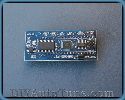
Processor installation and flashing
Insert the CPU U1 into the socket. Check the orientation mark to make sure that you've installed it correctly.
Now it'* time to load code on to the MS2 processor.
Get the latest version of MegaSquirt-II code here:
www.megamanual.com/ms2/code.htm
Download the correct firmware and downloader (the downloader is here) for your chip. Install the downloader by clicking on the file and following the instructions. Note that the V2.0+ versions of the downloader can get the latest code and INI from the internet and install them, if your PC has internet access. You can initiate this with the 'File/Upgrade' menu item.
To use the downloader.exe:
1. Power down MegaSquirt� EFI Controller,
2. Put the boot jumper on both pins of the header marker B/LD (for "bootloader") on the MegaSquirt-II (not the main board)
3. Power up MegaSquirt� (plug in the stim). The LEDs on MegaSquirt� will flash very briefly (if installed), then go out. This is proper response for the LEDs when the MegaSquirt-II goes into bootload mode (i.e. when the bootload jumper is on).
4. Start the downloader program, and select the appropriate COM port,
5. Select the appropriate .S19 file, and the downloader will read, write and verify the code to the processor in about 10 seconds or so.
6. The process ends with a message like "Verification succeeded, 999 records total (4 skipped)."
7. Shut down the downloader program.
8. Remove power from MegaSquirt� (disconnect the stim).
9. Remove the boot jumper (or put it on just one pin of the B/LD header for storage)
Software and Testing
Now it'* time to load the software on your computer. I recommend diyautotune'* tuning software package. http://www.diyautotune.com/softwarelinks.htm The software from diyautotune is already configured. Simply install the software and run Megatune. The first dialog box that pops up asks which code we have installed. Select MS2-MicroSquirt BG 2.890.
Go into the "Communications" window and select the proper COM port (the "Verify ECU operation" does not operate, so do not be fooled). Exit this screen.
Plug the stimulator into the ECU. On the PC using MegaTune, click the "Realtime Display" under "Tuning" on the main menu, which brings up a new screen. (Note that if you have MS-II 2.8+ code, you may have to set the 'ECU Type' under 'Fuel Set-Up/General' otherwise all other menu items may be 'greyed out'.) Look at the "Time(*)" near the top left corner of the Realtime Display - it should be counting up, incrementing every second (it will roll over at the value of 255, back to zero). If the seconds count is there, you are running! If not, check the cable, make sure there is power, and check the COM port. The only other value on the screen which is working correctly is the "Batt V" box - it should be displaying the battery voltage (from about 7.0 - 8.5 volts, depending on the 9-volt battery condition). All other boxes will have nonsense for numbers.
Inputs
Remove the processor from the 40-pin socket - use a thin screwdriver and pry it from the socket, first one end, then the other - place it back on the foam pad it was shipped with. Now, you are going to install all of the input sensor components.
Install and solder C3 {399-4329-ND, 0.1 �F, 104 marking}. This is located in the bottom right section of the board (near the DB37, furthest away from the heat sink) between the U2 column of holes and the SPR2(CANL)/SPR1(CANH) holes.
Install and solder C2, C9 and C10 {399-2083-ND or 399-4353-ND, 0.22 �F, 224 marking}. These install in the column of capacitors just above "Grippo" in the copyright notice on the silkscreen at the bottom of the board.
Install and solder C4, C6, and C8 {399-4202-ND, 0.001 �F, 102 marking}. These install in the column of capacitors just above "Grippo" in the copyright notice on the silkscreen at the bottom of the board.
Install and solder C5 and C7 {399-2102-ND or 399-4389-ND, 1.0 �F, 105 marking}. These install in the column of capacitors just above "Grippo" in the copyright notice on the silkscreen at the bottom of the board.
Install and solder R2, R9, and R10 {1.0KQBK-ND, 1K, brown-black-red}. These install in the column of resistors just above "&" in the copyright notice on the silkscreen at the bottom of the board.
Install and solder R5 and R8 {2.2KQBK-ND, 2.2K, red-red-red}. These install in the column of resistors just above "&" in the copyright notice on the silkscreen at the bottom of the board.
Install and solder R11 {1.0MEBK-ND, 1M, brown-black-green-gold). This installs in the column of resistors just above "&" in the copyright notice on the silkscreen at the bottom of the board.
Next is the Hall/Optical input circuit.
1. Install and solder R12 {390H-ND, 390 Ohm, � watt, orange-white-brown}. This is installed between the resistors you have just been installing and the CPU socket. This resistor should be mounted roughly 1/8" (2mm) above the surface of the PCB.
2. Install and solder R13 {4.7KEBK-ND, 4.7k, yellow-violet-red}. This is located 3 places close to the heat sink than R12 (which you just installed).
3. Install and solder C11 {399-2075-ND or 399-4326-ND, 0.01�F, 103 marking}. This installs at the top of the row of 'vertically' oriented capacitors above "Bowling" in the copyright notice.
4. Leave the C30 location empty - DO NOT jumper it.
5. Do not install D1, put a jumper in its place. It is located beside R12, further from the heat sink.
6. Do not install D2, install a jumper (made from a snipped off lead) in its place. It is located beside D1, closer to the heat sink.
7. Install/solder opto-isolator U3 {160-1300-5-ND, 4N25). This is located near the center of the PCB. Observe the proper orientation (notch matches PCB - towards the heat sink, or dot for pin #1 which is the square pad on PCB at the notched end of the silk screen). If neither are there, hold the chip so that the writing is facing you and the right way around. Pin #1 is on the bottom left.
8. Leave the C12 location empty - DO NOT jumper it. This is located above "Bowling" in the copyright notice.
Next install jumpers:
* Jumper XG1 to XG2 on the bottom side of the PCB, near the 40 pin socket,
* Jumper OPTOIN to TACHSELECT on the bottom side of the PCB, near the DB37 connector, opposite the heat sink.
* Jumper TSEL to OPTOOUT on the bottom side of the PCB, near the center.
Time to install the onboard MAP sensor. It mounts on the under side of the PCB, with the vacuum port facing the DB37 connector end of the PCB, and the markings on the sensor facing away from the PCB so you should be able to read the "MPX4250AP" marking when the sensor is installed. The leads are bent toward the PCB, and soldered on the top-side. The notch on the lead indicates pin #1 - this corresponds to the square pad on the PCB.
The MAP sensor is held to the PCB with two nylon screws - do not tighten the MAP sensor too tight, this will distort the case and introduce an offset in the readings by flexing the load cell inside the device. And, yes, solder the leads on the top side of the PCB. You will have to devise a scheme to run a tube from the barbed MAP fitting to your intake manifold.
Install and solder R4 and R7 {2.49KXBK-ND, 2.49K, red-yellow-white-brown-brown). These are the temperature sensor "bias" resistors. They install above the "&" in the copyright notice.
Testing inputs is important to make sure you built everything correctly. Directions for testing can be found on the megamanual V3.0 assembly instructions - Step 55.
First step is to plan and buy your megasquirt. I used a v3.0 board and a MS2 processor. http://www.diyautotune.com
Currently, the latest board release is v3.57 and processor is MS3. However, you do not need a v3.57 board to install a MS3 processor. It will work for either board version.
I recommend a V3.0 board because it currently has the best documentation. However, the 3.57 board is pre-assembled if you are not handy with a soldering iron. If you choose a 3.57 board, you need to know this information to use this write-up.
$430 - V3.57 with MS2
$253 - V3.0 no processor included
Processor choice is completely up to you.
The MS2 processor has the best documentation and is easy to set up and use. However, it only has a limited number of inputs and outputs and cannot handle advanced engine operations like sequential fuel injection.
$96
The MS3 processor is very new and much more advanced. It is highly expandable and is for a true enthusiast.
$199 This article however, only covers the MS2 processor.
If you plan on using an electronic transmission, you need to buy and build the GPIO and then install the components for MegaShift. This article is written for a non-electric trans with Torque Converter Clutch.
$235 plus $26 for the Megashift components.
You can optionally buy the Megastim. The stimulator acts as a 'digital car' and is used for assembly/testing/flashing purposes. I highly recommend you buy/build one. It can be good practice if you haven't used a soldering iron in a while.
$45
Assembly
A lot of the information in this write-up is word for word from Megamanuals V3 assembly guide. But I'll just use the information that'* relevant to GM V6s.
You will be referencing this image a lot to identify locations of the components as you are installing them. I recommend you print it.
Power circuit
Install and solder the male DB-37 header (P2) {A23289-ND or A32103-ND} on the PCB. The connectors require a bit of force to 'snap' them into place. Solder all of the pins to give the headers the maximum physical strength. Then install and solder the female DB-9 header (P1) {A23305-ND or A32119-ND}.
Next, install the 40-pin DIP socket {AE7240-ND or AE10018-ND} for the processor - notice that the notch installs near the bottom of the board, corresponding to the PCB silk screen. The socket must be installed from the top of the board, and soldered from the bottom side. To prevent the socket from falling out while you turn the board upside down and solder, you can use a bit of scotch tape across the socket to hold it in place (this works for many of the ICs and some other components). Carefully solder the socket, and inspect each solder joint for shorts (to adjacent pins) or cold joints (solder applied to a joint the isn't hot enough to flow properly, typically they won't have a nice 'cone' to the solder).
Next, you are going to install the components that make up the power supply, and then verify operation. The first part to install is the 'Perry' Metal Oxide Varistor MOV1 {P7315-ND}. This is a large flat disc, about an inch (~25mm) in diameter. It is soldered near the DB37 connector, and does not have a polarity, it can go either way around. This part protects the MegaSquirt� from surges on the 12 volt line.
Install the capacitor C15 {399-4202-ND, 0.001 �F, 102 marking}. This goes near the MOV1 you just installed, between it and "Grippo" in the copyright notice.
Install and solder C16 {399-1420-ND or 399-3584-ND, a tantalum capacitor, 22 microFarads (�F), 226 marking} - make sure polarity is observed. It has a small “+” near the positive lead. The longer lead is also always the positive lead. It is located next to the DB9 connector.
Install and solder C17 {399-1420-ND or 399-3584-ND, tantalum, 22 �F} - make sure polarity is observed. The longer lead is positive on all of the capacitors. It is located next to the C16 capacitor you just installed, near the DB9 connector.
Install and solder C18 {399-4329-ND, 0.1 �F, 104 marking}. This installs near the DB9 connector, just above (closer to the heat sink area) the C17 capacitor you installed in the last step.
Install and solder C19 {399-4329-ND, 0.1 �F capacitor, 104 marking}. This installs near the CPU #1 pin.
Install and solder C23 {399-4329-ND, 0.1 �F capacitor}. This installs near CPU pin #21.
Install and solder C22 {399-3559-ND, 4.7 �F electrolytic} - make sure polarity is observed. It is located very close to C23.
Install and solder D9 {1N4001DICT-ND} - make sure banded end is installed correctly as per board. This installs near the DB9 connector, very near U5 on the heat sink. To do this, make sure the end of the diode with the band on it goes to the end of the silkscreen (at D9) that has the band nearest it.
Install and solder D10 {1N4001DICT-ND} - make sure banded end is installed correctly as per board. This is installed near the MOV1 you installed earlier.
Install and solder diode D11 {1N4001DICT-ND} - make sure banded end is installed correctly as per board. This is installed near the MOV1 you installed earlier.
Install and solder D12 {1N4749ADICT-ND, 24 volt Zener} - make sure banded end is installed correctly as shown on the printed circuit board. This installs very near D10 and D11.
Install and solder diode D13 {1N4742ADICT-ND, 12 volt Zener, 1N4742 marking} - make sure banded end is installed correctly as per the board. It is located above the column of capacitors above "Grippo" in the copyright notice.
Install and solder diode D19 {1N4734ADICT-ND, 5.6 volt Zener, 1N4734 marking} - make sure banded end is installed correctly as per the board. It is located in the upper right section of the board (near the DB37 and heat sink), below the Q14 and Q10 transistor and R32, R30 & R31 resistors.
Install and solder L1 {M8388-ND, inductor, 1�H, small coil of wire with leads}. It is installed near the notched end of the CPU socket. Space the inductor about 1/8” (3mm) off the PCB to avoid shorts on the traces underneath.
Install and solder L2 {M8388-ND, inductor, 1�H}. It is installed between the CPU socket and the DB9 connector. Space the inductor about 1/8” (3mm) off the PCB to avoid shorts on the traces underneath.
Install and solder F1 and F2 {RXEF050-ND}. These are � Amp poly fuses (small yellow discs that look similar to some capacitors) that acts like a circuit breaker on the 5 Volt supply to the PCB from the regulator. F1 installs very near the DB9, in the middle of some of the capacitors you have already installed. F2 installs near the center of the DB37 connector, and very close to it.
Install the voltage regulator U5 {LM2937ET-5.0-ND}. This part installs near the DB9 connector on the top of the board. Use heat-sink compound on the tab, and use the nylon screw and nut to fasten to the PCB. The leads go through the board and are soldered on the top side.
Install a jumper from the hole marked S12C to the hole marked JS9 (+12C). These are on the bottom side of the board, on the DB9 side of the processor.
Connect the following jumper wires to control your GM IAC valve:
* Connect (1A)JS0 (under the processor socket) to IAC1A (near the DB37 connector) - this brings out IAC1A on DB37 pin #25
* Connect (1B)JS1 (under the processor socket) to IAC1B (near the DB37 connector) - this brings out IAC1B on DB37 pin #27
* Connect (2A)JS2 (under the processor socket) to IAC2A (near the DB37 connector) - this brings out IAC2A on DB37 pin #29
* Connect (2B)JS3 (under the processor socket) to IAC2B (near the DB37 connector) - this brings out IAC2B on DB37 pin #31
Since we will be using an ignition output signal to control an ignition module with MS-II, jumper JS10 to IGBTIN, then jumper IGBTOUT to IGN. JS10 is on the bottom side of the board under the processor slot.
If you want to use CAN communications (if you plan on using an electronic trans and plan on building a GPIO board to control it), jumper JS6 to SPR1/CANH and JS8 to SPR2/CANL
Testing the power circuit is important to make sure you built everything correctly. Directions for testing can be found on the megamanual V3.0 assembly instructions - Step 23.
Serial Communications Circuit
First step, install capacitors C26, C27, C28, and C29, {all 399-4329-ND, 0.1 �F, 104 marking} by soldering them in the appropriate locations near the DB9 connector.
Next, solder the serial communication MAX232, U6 {497-2055-5-ND} - note the proper orientation on the silk-screening.
Testing the com circuit is important to make sure you built everything correctly. Directions for testing can be found on the megamanual V3.0 assembly instructions - Step 26.
Clock Circuit
Install C1 {399-4329-ND, 0.1 �F, 104) and solder. This is located near pin #20 of the CPU socket.
Install and solder C20 {399-4361-ND, 0.033 �F, 333 marking}. It is located in a row of three capacitors above the L1 inductor you installed (above ".info" in the copyright notice)
Install and solder C21 {399-2075-ND or 399-4326-ND, 0.01 �F, 103 marking}. It installs beside C20.
Install and solder C24 {399-1911-ND, 47 pF, 470 marking}. This installs on the other side of C20.
Install and solder C25 {399-1908-ND, 22 pF, 220 marking}. This installs near the Y1 square silkscreen pad.
Install and solder R1 {10KEBK-ND, 10K, brown-black-orange}. This installs near pin #18 of the CPU socket. Resistors do not have a polarity, so they can go either way around.
Install and solder R3 {51KEBK-ND, 51K, green-brown-orange-gold/silver). This installs near pin #21 of the CPU socket.
Install and solder R6 {10KEBK-ND, 10K, brown-black-orange}. This installs near L2, by the 'Boot' jumper hole.
Install and solder R21 {10KEBK-ND, 10K, brown-black-orange}. This installs between C20 and C25.
Install and solder R22 {100KEBK-ND, 100K, brown-black-yellow}. This installs between the pad for Y1 and the components you have already installed nearby.
Install and solder R23 {10MEBK-ND, 10M, brown-black-blue}. This installs between the Y1 pad and the CPU socket.
Install and solder Y1 {300-1002-ND, 32768 Hz crystal, the very small silver can with the two tiny wires}. Note that Y1 is physically fragile, do not drop it. The crystal will fail to operate if it touches other components, so be sure it is clear of these. Bend the leads at a 90-degree angle so that the crystal lies parallel to the PCB. Note: You may want to “glue” the crystal to the printed circuit board with a cushion of silicone rubber adhesive (RTV) or 'hot glue'. A small "blob" on the under side of the crystal will cushion the crystal and dampen any mechanical vibrations. A small metallic ground pad is provided for this purpose.
Processor installation and flashing
Insert the CPU U1 into the socket. Check the orientation mark to make sure that you've installed it correctly.
Now it'* time to load code on to the MS2 processor.
Get the latest version of MegaSquirt-II code here:
www.megamanual.com/ms2/code.htm
Download the correct firmware and downloader (the downloader is here) for your chip. Install the downloader by clicking on the file and following the instructions. Note that the V2.0+ versions of the downloader can get the latest code and INI from the internet and install them, if your PC has internet access. You can initiate this with the 'File/Upgrade' menu item.
To use the downloader.exe:
1. Power down MegaSquirt� EFI Controller,
2. Put the boot jumper on both pins of the header marker B/LD (for "bootloader") on the MegaSquirt-II (not the main board)
3. Power up MegaSquirt� (plug in the stim). The LEDs on MegaSquirt� will flash very briefly (if installed), then go out. This is proper response for the LEDs when the MegaSquirt-II goes into bootload mode (i.e. when the bootload jumper is on).
4. Start the downloader program, and select the appropriate COM port,
5. Select the appropriate .S19 file, and the downloader will read, write and verify the code to the processor in about 10 seconds or so.
6. The process ends with a message like "Verification succeeded, 999 records total (4 skipped)."
7. Shut down the downloader program.
8. Remove power from MegaSquirt� (disconnect the stim).
9. Remove the boot jumper (or put it on just one pin of the B/LD header for storage)
Software and Testing
Now it'* time to load the software on your computer. I recommend diyautotune'* tuning software package. http://www.diyautotune.com/softwarelinks.htm The software from diyautotune is already configured. Simply install the software and run Megatune. The first dialog box that pops up asks which code we have installed. Select MS2-MicroSquirt BG 2.890.
Go into the "Communications" window and select the proper COM port (the "Verify ECU operation" does not operate, so do not be fooled). Exit this screen.
Plug the stimulator into the ECU. On the PC using MegaTune, click the "Realtime Display" under "Tuning" on the main menu, which brings up a new screen. (Note that if you have MS-II 2.8+ code, you may have to set the 'ECU Type' under 'Fuel Set-Up/General' otherwise all other menu items may be 'greyed out'.) Look at the "Time(*)" near the top left corner of the Realtime Display - it should be counting up, incrementing every second (it will roll over at the value of 255, back to zero). If the seconds count is there, you are running! If not, check the cable, make sure there is power, and check the COM port. The only other value on the screen which is working correctly is the "Batt V" box - it should be displaying the battery voltage (from about 7.0 - 8.5 volts, depending on the 9-volt battery condition). All other boxes will have nonsense for numbers.
Inputs
Remove the processor from the 40-pin socket - use a thin screwdriver and pry it from the socket, first one end, then the other - place it back on the foam pad it was shipped with. Now, you are going to install all of the input sensor components.
Install and solder C3 {399-4329-ND, 0.1 �F, 104 marking}. This is located in the bottom right section of the board (near the DB37, furthest away from the heat sink) between the U2 column of holes and the SPR2(CANL)/SPR1(CANH) holes.
Install and solder C2, C9 and C10 {399-2083-ND or 399-4353-ND, 0.22 �F, 224 marking}. These install in the column of capacitors just above "Grippo" in the copyright notice on the silkscreen at the bottom of the board.
Install and solder C4, C6, and C8 {399-4202-ND, 0.001 �F, 102 marking}. These install in the column of capacitors just above "Grippo" in the copyright notice on the silkscreen at the bottom of the board.
Install and solder C5 and C7 {399-2102-ND or 399-4389-ND, 1.0 �F, 105 marking}. These install in the column of capacitors just above "Grippo" in the copyright notice on the silkscreen at the bottom of the board.
Install and solder R2, R9, and R10 {1.0KQBK-ND, 1K, brown-black-red}. These install in the column of resistors just above "&" in the copyright notice on the silkscreen at the bottom of the board.
Install and solder R5 and R8 {2.2KQBK-ND, 2.2K, red-red-red}. These install in the column of resistors just above "&" in the copyright notice on the silkscreen at the bottom of the board.
Install and solder R11 {1.0MEBK-ND, 1M, brown-black-green-gold). This installs in the column of resistors just above "&" in the copyright notice on the silkscreen at the bottom of the board.
Next is the Hall/Optical input circuit.
1. Install and solder R12 {390H-ND, 390 Ohm, � watt, orange-white-brown}. This is installed between the resistors you have just been installing and the CPU socket. This resistor should be mounted roughly 1/8" (2mm) above the surface of the PCB.
2. Install and solder R13 {4.7KEBK-ND, 4.7k, yellow-violet-red}. This is located 3 places close to the heat sink than R12 (which you just installed).
3. Install and solder C11 {399-2075-ND or 399-4326-ND, 0.01�F, 103 marking}. This installs at the top of the row of 'vertically' oriented capacitors above "Bowling" in the copyright notice.
4. Leave the C30 location empty - DO NOT jumper it.
5. Do not install D1, put a jumper in its place. It is located beside R12, further from the heat sink.
6. Do not install D2, install a jumper (made from a snipped off lead) in its place. It is located beside D1, closer to the heat sink.
7. Install/solder opto-isolator U3 {160-1300-5-ND, 4N25). This is located near the center of the PCB. Observe the proper orientation (notch matches PCB - towards the heat sink, or dot for pin #1 which is the square pad on PCB at the notched end of the silk screen). If neither are there, hold the chip so that the writing is facing you and the right way around. Pin #1 is on the bottom left.
8. Leave the C12 location empty - DO NOT jumper it. This is located above "Bowling" in the copyright notice.
Next install jumpers:
* Jumper XG1 to XG2 on the bottom side of the PCB, near the 40 pin socket,
* Jumper OPTOIN to TACHSELECT on the bottom side of the PCB, near the DB37 connector, opposite the heat sink.
* Jumper TSEL to OPTOOUT on the bottom side of the PCB, near the center.
Time to install the onboard MAP sensor. It mounts on the under side of the PCB, with the vacuum port facing the DB37 connector end of the PCB, and the markings on the sensor facing away from the PCB so you should be able to read the "MPX4250AP" marking when the sensor is installed. The leads are bent toward the PCB, and soldered on the top-side. The notch on the lead indicates pin #1 - this corresponds to the square pad on the PCB.
The MAP sensor is held to the PCB with two nylon screws - do not tighten the MAP sensor too tight, this will distort the case and introduce an offset in the readings by flexing the load cell inside the device. And, yes, solder the leads on the top side of the PCB. You will have to devise a scheme to run a tube from the barbed MAP fitting to your intake manifold.
Install and solder R4 and R7 {2.49KXBK-ND, 2.49K, red-yellow-white-brown-brown). These are the temperature sensor "bias" resistors. They install above the "&" in the copyright notice.
Testing inputs is important to make sure you built everything correctly. Directions for testing can be found on the megamanual V3.0 assembly instructions - Step 55.
 02-07-2011, 08:53 AM
#2
Senior Member
True Car Nut
Thread Starter
Join Date: Jul 2010
Location: Danville, Illinois
Posts: 2,469
Likes: 0
Received 0 Likes
on
0 Posts
Outputs
Install and solder R14 and R17 {10KEBK-ND, 10K Ohm, brown-black-orange). These are located near the center of the PCB, in the column of components roughly aligned with Q9 on the heat sink.
Install and solder R16, R19, R26, R27, and R29 {1.0KEBK-ND, 1K Ohm, brown-black-red}. R16 is near the MOV1 (but a bit further away from the DB37 connector). R19 is to the right (closer to the DB37 connector) of the resistors you installed in the last step (R14 & R17) on the other side of C13 and C14. R26, R27, & R29 are located near the LEDs at the DB9 end of the PCB.
Install and solder D3 {1N4001DICT-ND}. This is located near the center of the PCB, near R14 and R17. Observe the proper polarity.
Install and Solder D4 and D8 {1N4748ADICT-ND} - observe the proper polarity. These are located beside MOV1, a bit further away from the DB37 connector.
Install and solder R15 and R20 {22QBK-ND, 22 Ohm, red-red-black}. R15 is located below the Q1 location on the heat sink, R20 is located below the R38 location on the heat sink.
Install and solder R24, R25, and R28 {330QBK-ND, 330 Ohm, orange-orange-brown). These are located very near the LEDs on the DB9 end of the PCB.
Install and solder the transistors Q2 and Q4 {ZTX450-ND}. These are located to the left of the MOV1. The side of the transistor with the white label faces the DB37 connector. If you got this transistor from a distributor (as part of a kit) then they likely have special instructions for it (search the packaging or contact the distributor). Distributors sometimes make substitutions for various reasons, and thus their notes are important. If your Q2/Q4 are the standard Digi-Key part {ZTX450-ND}, but don't have a white label, then the side with the rounded edges is the 'curved side', which is oriented to be closest to the DB37 connector.
Install C13 {399-4329-ND, 0.1 �F, 104) - and solder. This is located a bit closer to the heat sink, and a bit closer to the DB9 than Q4.
Install and solder C14 {399-3559-ND, 4.7 �F). This is located just a bit further away from the heat sink than C13, which you installed in the last step. Observe polarity. Recall that the positive lead has a small + near it on the body of the capacitor.
Install and solder U4 {IXDI404PI-ND}, the FET driver. This is located near the Q3 location on the heat sink. If you bought a socket {AE7208-ND}, solder it in place and insert the chip. Be sure to orient it correctly, the notch or dot on the chip goes to the notched end on the silkscreen; this end is closest the heat sink.
Install D17 and D18 {1N5819DICT-ND}, the Schottky diodes. These are located on either side of the FET driver (U4) you just installed. Make sure the band on the diode matches the silkscreen.
Install and solder D21 {1N4753ADICT-ND}. This is located just a bit further away from the heat sink than D17. Make sure the band on the diode matches the silkscreen.
The following are directions for installing the PWM flyback dampening circuit. This will allow you to run either high or low impendence injectors.
Install R30, R31, R34 and R35 {270QBK-ND, red-violet-brown}. R30 and R31 are near R37 on the heat sink, R34 and R35 are near Q9.
Install R32 and R36 {1.0KQBK-ND, 1K Ohm, brown-black-red}. These are located besides the resistors you installed in the last step.
Install Q9 and Q12 {TIP125TU-ND}. Bend the leads to fit in the holes so that the hole in the tab lines up with the hole in the heat sink. These transistors mount to the heat sink, but they MUST have an insulator between the transistors and the heat sink. Use the insulator kits for this {4724K-ND}. You may have to trim the mica insulator somewhat to avoid hitting the transistor leads - use a sharp pair of scissors. Use heat transfer compound between the component, mica insulator, and the heat sink.
Install Q10 and Q13 {2N3904FS-ND}. The flat side of the transistors face the heat sink. These are located near Q9 and R37 on the heat sink. The pins are very close together, use a clean tip, and be careful not to bridge the joints.
Then install the standard flyback circuit
Install R18 and R33 {270QBK-ND, red-violet-brown}. These are located below R38 and Q1 on the heat sink.
Install D6 and D20 {1N4753ADICT-ND}. These are located beside the resistors (R18, R33) you just installed. Make sure the band on the diode matches the silkscreen.
Install Q3 and Q11 {497-2629-5-ND}. These mount to the heat sink. No insulator kit is necessary, the tab can contact the heat sink. Use heat transfer compound between the component and the heat sink.
Now install the current limiting circuit
Install R37 {TAH20PR050JE-ND}. It goes on the heat sink, however it does not have a mounting hole. You can use double sided thermal transfer tape {BER158-ND} to fasten it to the heat sink, however this is quite expensive if you are just doing two resistors.
Install R38 {TAH20PR050JE-ND}. It goes on the heat sink as well, however it does not have a mounting hole. You can use double sided thermal transfer tape {BER158-ND} to fasten it to the heat sink, however this is quite expensive if you are just doing two resistors.
Then install Q14 and Q15.
Install D5 and D7 {FR302DICT-ND}. These diodes should be mounted about 1/8" to 1/16" off the board. Make sure the band on the diode matches the silkscreen. These are located near R38 and Q3.
Install Q19 and Q20 {2N3904FS-ND}. These are located in line with the existing transistors (Q2 and Q4) to the left of the MOV1. Be very careful when soldering them, use a clean tip, as the pin spacing is very tight.
Install R39 and R40 {1.0H-ND, 1 Ohm, brown-black-gold}. These are located on either side of the transistors (Q19 & Q20) that you installed in the last step.
Install Q1 and Q5 {IRFIZ34GPBF-ND}, the FETs (field effect transistors, used to drive the injectors). These are bolted to the heat sink, be sure to use heat transfer compound between the FET and the heat sink. These are insulated case variety, so they mount directly on the heat sink.
Install and solder Q6, Q7, and Q8 {2N3904FS-ND}. Follow the silkscreen to orient the flat side of these transistors, which faces the DB9 end of the PCB.
Now assemble the case and mount the LEDs - D14, D15, and D16 {P301-ND} to the case font, and bend the leads down to the board and solder. The flats on the LEDs (the side with the short lead) faces the DB9 connector. First, install the LED holders on the front panel, through the front. Next, the LEDs press into the rear of the holder. Mount the case front panel to the case half (which has the PCB). Orient the FLAT on the side of the LED lip (the side with the shorter lead) towards the DB-9 socket (each LED). You will see that the PCB silk screen also has a "dash" above the LED circle symbol indicating the side of the flat. Bend the LED leads down to enter the PCB holes for them - you will have to do a trial fit, then trim the leads down a bit. See the illustrations below. Then solder the LEDs to the PCB from the top of the PCB. It is a little tricky - take your time.
Your megasquirt is now completed.
Installation
Wiring the megasquirt into the vehicle is a unique challenge. I highly recommend using a factory engine harness and tapping into the factory ECM plugs. Leave them intact in the event you ever need to go back to stock. The following diagram will help you get started.
GM DIS
* Module pin B or C - white wire - DB37 #36 (V3 main board, ignition output signal pin for V2.2),
* Module pin A - tan/black wire - Connect to a bypass relay as shown for the HEI modules
* Module pin E - purple/white wire - DB37 pin #24 (tach),
* Module pin F - red/black wire - ground,
* Module separate connector - black/white - ground,
* The module also has connections for power (pink), the crank position sensor (yellow & purple), and tach (white).
Note on the bypass relay http://www.megamanual.com/ms2/GM_7pinHEI.htm
I installed this relay but never needed it. I did not have a problem starting the car with this relay not installed. If you are unable to start the car, install this relay.
GM DIS needs a dwell setting of 25ms. To set the dwell to 25.0, you'll have to change the megasquirt-II.ini file which can be found at C:\Program Files\Megasquirt\MS2-MicroSquirt BG 2.890. Edit the following line with Notepad.exe (installed on most Windows systems, look under 'Start/All Programs/Accessories') or a similar text editor:
max_coil_dur = scalar, U08, 4, "ms", 0.10000, 0.00000, 1.00, 8.00, 1 ; * ( 1 byte)
to
max_coil_dur = scalar, U08, 4, "ms", 0.10000, 0.00000, 1.00, 25.50, 1 ; * ( 1 byte)
Fuel Pump Relay
After you've wired in your MS and key on, the megasquirt should turn on. When it turns on you should hear the fuel pump relay click and the fuel pump should run. If it does not, it'* because your GM ECM triggered the fuel pump relay with a + signal. The megasquirt uses a - to trigger the relay. So you may need to switch pin 86 to a 12V+.
Using a non-electric trans with a Torque Converter Clutch (TCC)
You can wire the TCC to pin 30 (fast idle) on the DB37. Settings for software will come later.
Spare Ports (Fans, etc)
http://www.megamanual.com/ms2/spare.htm
If you have any problems wiring in your MS, refer to http://www.megamanual.com/v22manual/mwire.htm
Megatune
Here is the article for setting up Megatune: http://www.megamanual.com/ms2/configure.htm
First, make a new folder in the ProgramFiles/Megasquirt/ directory. Give it a unique name, aka. Turbo Grand Prix. Then go into the MS2-MicroSquirt BG 2.890 and copy the entire contents. Paste them into your new folder. Now when you start Megatune, you will see the option to select your car from the menu.
I will go ahead and give you the settings that I'm currently using.
Starting with 'Fuel Set-Up'
General
ECU Type = 1
Engine Displacement = 213 (whatever your displacement is)
Injection Timing Delay = 0
Dual Table Use = Single Table
Barometric Correction = Initial MAP Reading
X-Tau Usage = Off
Prime, ASE, WUE, Baro Tables = Two-Point
MAP Lag = 50
RPM Lag = 50
TPS Lag = 75
Lambada Lag = 60
CLT/IAT/Battery Lag = 50
Knock Lag = 80
TPS Sampling Rate = 25
MAP Sampling Rate = 25
Idle Control
Algorithm = IAC Stepper Moving
Time Step Size = 2.5
Acceleration Step Size = 0
Minimum # of steps = 1
Start Value = 160
Cranking Position = 100
Crank to Run Taper Time = 5
Hysteresis = 5.0
Cold Temp 0.0
Cold Position 120
Cold Taper 40
Spare Port Settings
If you wanted to use the FIdle output as a TCC control, and the accel LED as an indicator that the TCC is active, you would set:
* FIdle (PM2):
o Port PM2, enabled
o variable = map < threshold = 75, hysteresis = 10,
o AND
o variable = coolant > threshold = 160, hysteresis = 10,
o Power-on value = 0
o Trigger value = 0
* Accel LED (PM4):
o Port PM4, enabled
o variable = map < threshold = 75, hysteresis = 10,
o AND
o variable = coolant > threshold = 160, hysteresis = 10,
o Power-on value = 0
o Trigger value = 1
Example: Torque Converter Clutch Control
Suppose you want to engage OD (overdrive) over 50 kPa MAP, and engage the LU (torque converter lock-up) clutch at 75 kPa MAP, provided temp is over 140 and RPM is over 2000. For a torque converter clutch control (TCC) using FIdle with 3 conditions (rpm > 1500, CLT > 160, map < 75), set:
PA0 - Knk Enable:
* rpm > 1500
* coolant > 160
and
PM2 - FIdle:
* map < 75
* port0 > 63
Injector Characteristics
Injector Open Time = 1
Battery Voltage Correction = .20
PWM Current Limit = 100
PWM Time Threshold = 25.5
Injector PWM = 66
Injector Control
Use the Required Fuel button
Control Algorithm = Speed Density
Injections per cycle = 2
Injector Staging = Alternating
Engine Stroke = Four-Stroke
Number of cylinders = 6
Injector Port Type = Port Injection
Injectors = 6
Rev Limiter
Algorithm = Fuel Cut
Lower Limit = 5800
Upper Limit = 6000
AfterStart Enrichment
ASE Hot Start = Disable
ASE Cold% = 65
ASE Hot% = 25
ASE Cold Count = 320
ASE Hot Count = 150
Accel Enrichment
Low RPM = 1500
High RPM = 5000
Other Fuel
Cranking RPM = 300
Use MAP/baro tables = Use MAP only
AFR Table Fuel Calc - Seperate VE & AFR
AFR stioch volts = 0.5 <--- I use a NBo2
Prime Pulse Cold = 6.5
Prime Pulse Hot = 2
Prime Delay = 0
N2O Enrichment % = 0
Spark Retard N2O = 0
EGO Control
EGO Sensor Type = Narrow Band
NB Voltage Target = 0.5000
Ignition Events = 33
Controller step = 2
Controller Authority = 8
Active temp = 90
Active RPM = 1500
Active below TPS = 70
Active below MAP = 80
I use a NB o2. You should not enable EGO Control until after you have a working tune.
Ignition Set-Up
Base Ignition Settings
Trigger Offset = 0
Skip Pulses = 3
Predictor Algorithm = Alpha-Beta-Gamma
Alpha % = 90
Beta % = 80
Gamma % = 10
Time Mask = 0
Percentage mask = 50
Cranking % = 50
After-Start % = 70
Normal Running % = 25
Check Tach Sync Options = Check Always
Ignition Input Capture = Rising Edge
Cranking Trigger = Trigger Rise
Coil Charging Scheme = Standard Coil Charge
Spark output = Going High Inverted
Dwell Settings
Maximum Dwell Duration = 3.1
Maximum Spark Duration = 2.0
Acceleration Compensation = 0.6
Volt 1 = -4
Volt 2 = -2
Volt 3 = 0
Volt 4 = 2
Volt 5 = 4
Duration 1 = 2.4
Duration 2 = 0.9
Duration 3 = 0.0
Duration 4 = -0.5
Duration 5 = -0.9
Advanced Ignition Options
Trigger Wheel Teeth = 0
Dual Spark Options = No dual spark
Offset = 0.0
Start IAT retard = 800
Full IAT retard = 1500
FET Output = 0
VR Input = 0
That should get you started. Now you need to make a spark table and a VE table. You can start tuning using this http://www.megamanual.com/ms2/tune.htm
Good Luck!
02-07-2011, 02:17 PM
#4
Senior Member
True Car Nut
Thread Starter
Join Date: Jul 2010
Location: Danville, Illinois
Posts: 2,469
Likes: 0
Received 0 Likes
on
0 Posts
This is not, and will not be a debate on which is better. This is an informative how-to.
There is not an advantage to using MS over a GM PCM for most people. But if you want to know what a megasquirt can do that a OBD1 GM PCM cannot, here'* a small list.
Variable Valve Timing, Variable Intake Timing, Coil Near Plug (or COP), low or high impendence injectors, flex fuel, launch control, flat-shift, SD card datalogging, two stage nitrous, dual WBo2 inputs, boost control, staged injection, plus extra outputs that can be programed to control anything you want, even if it requires PWM.

Thread
Thread Starter
Forum
Replies
Last Post

