1993 Throttle Body porting.....the finishing EXTREME touches
 08-18-2005, 12:49 AM
#1
Junior Member
Posts like a Ricer Type-R
Thread Starter

This is the Zilla'* TB. Many of you know that I took Damemorder'* lead on cutting out half the MAF support some time ago. I finally took it that little extra step tonight, last minute touches before it goes back on the car.
When the throttle is open, our TB'* have the heads of two screws exposed that hold the Throttle plate. Also, the face of one side of the shaft is milled flat for the screws. So what if the throttle is at WOT? the heads of two screws and the BOTTOM half of the throttle shaft are a restriction. What if you milled the opposite side of the shaft flat as well? What if you countersunk and put in flathead screws? Gain maybe 2% flow? What the hell, nothing to lose, and my own labor is free.
Zilla TB, already ported for the MAF support, before milling the shaft (note the round throttle shaft in this view):
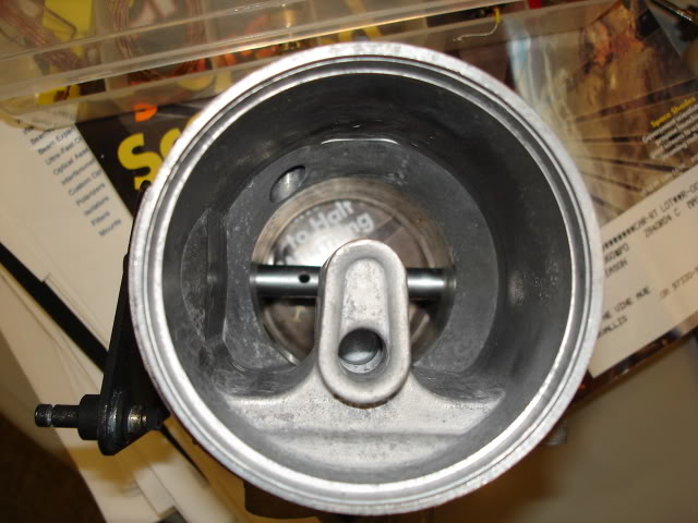
Opposite end of the TB (note the OEM flat for the screws that hold the plate in this view):
Also before milling. Due to focus, you can barely discern the flat side of the shaft and the opposite round side before milling:
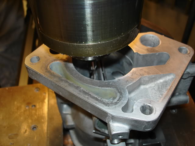
Let the milling commence:
Spare STOCK throttle body showing pan-head screws sticking up (these are exposed from the side at WOT):
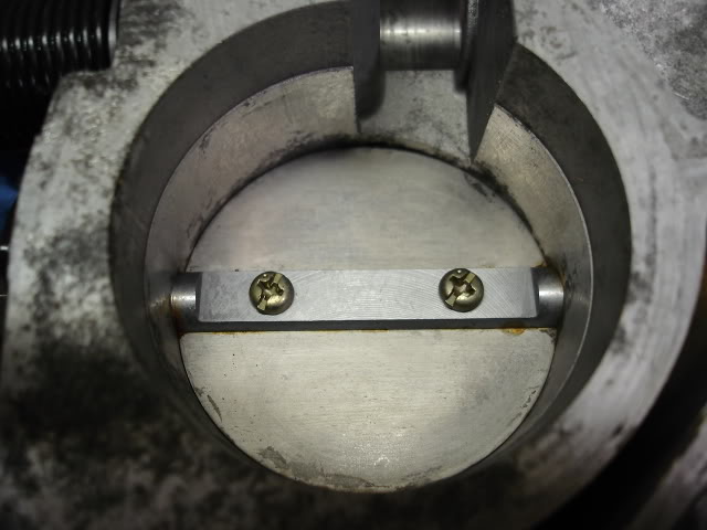
Same view of the Zilla'* TB after countersinking flathead screws:
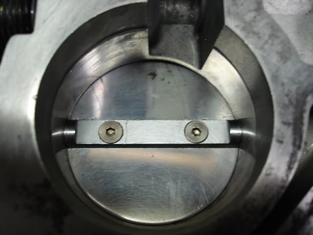
View of the new flat on the formerly round half of the shaft:
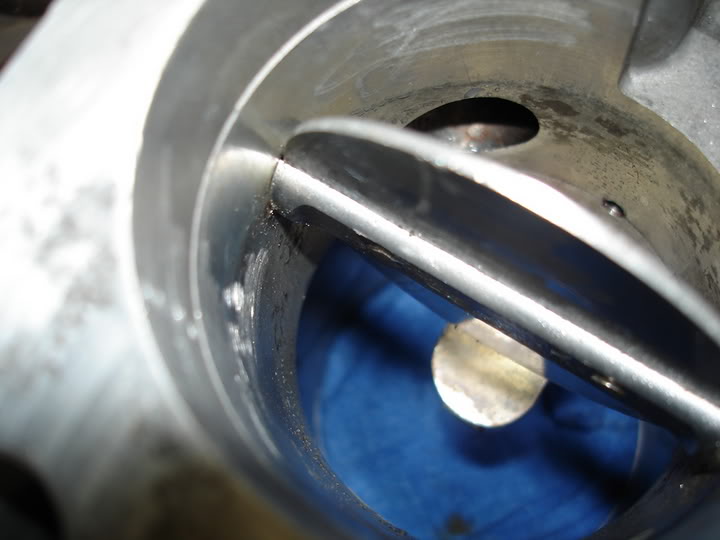
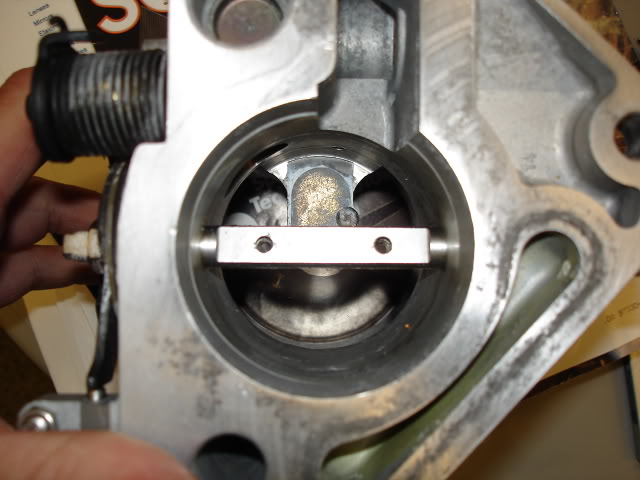
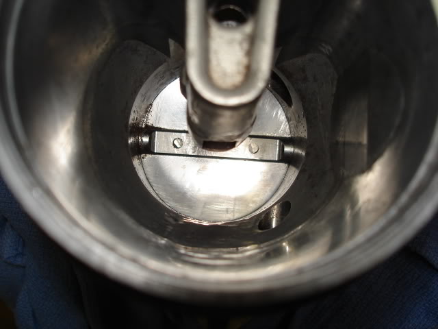
View into the STOCK TB, showing the round half of the shaft:
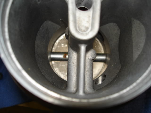
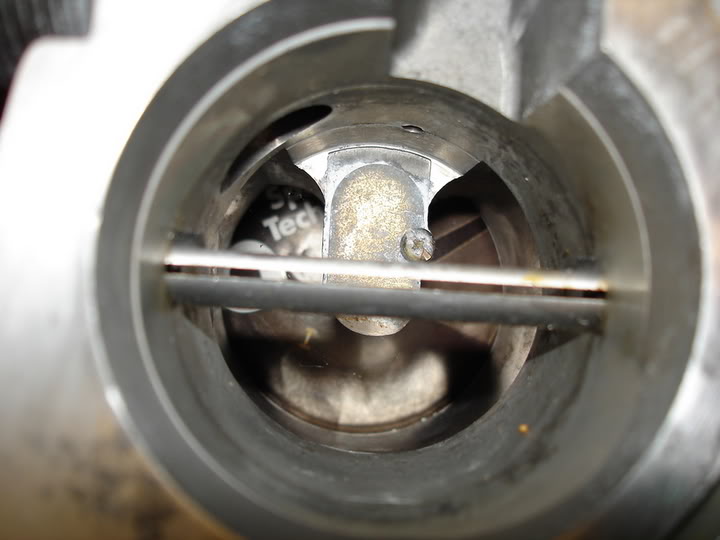
Same view of the Zilla'* TB, clearly showing the Porting and Milling:
If you're going to do it, go all the way.
When the throttle is open, our TB'* have the heads of two screws exposed that hold the Throttle plate. Also, the face of one side of the shaft is milled flat for the screws. So what if the throttle is at WOT? the heads of two screws and the BOTTOM half of the throttle shaft are a restriction. What if you milled the opposite side of the shaft flat as well? What if you countersunk and put in flathead screws? Gain maybe 2% flow? What the hell, nothing to lose, and my own labor is free.
Zilla TB, already ported for the MAF support, before milling the shaft (note the round throttle shaft in this view):
Opposite end of the TB (note the OEM flat for the screws that hold the plate in this view):
Also before milling. Due to focus, you can barely discern the flat side of the shaft and the opposite round side before milling:
Let the milling commence:
Spare STOCK throttle body showing pan-head screws sticking up (these are exposed from the side at WOT):
Same view of the Zilla'* TB after countersinking flathead screws:
View of the new flat on the formerly round half of the shaft:
View into the STOCK TB, showing the round half of the shaft:
Same view of the Zilla'* TB, clearly showing the Porting and Milling:
If you're going to do it, go all the way.
 08-18-2005, 01:00 AM
#2
Senior Member
True Car Nut

Join Date: May 2003
Location: Lethbridge, Alberta, _______Canada._______ West Coast Bonneville Fest ___05,06,07 Survivor___
Posts: 8,135
Likes: 0
Received 0 Likes
on
0 Posts

Wow, thats a VERY good idea actually, less restriction, what the hell eh?!
Tomorrow my TB is coming off as well for a cleaning btw....
.....Your car is gunna be goin soon i hope
Tomorrow my TB is coming off as well for a cleaning btw....
.....Your car is gunna be goin soon i hope
08-18-2005, 01:05 AM
#3
Senior Member
Posts like a Supercharger

Join Date: Jul 2005
Location: Zimmerman, MN.
Posts: 198
Likes: 0
Received 0 Likes
on
0 Posts
You missed a spot. The inlet of the T/B needs to be ground and polished to a sharp edge inorder to make a seamless flow from the intake tube to the T/B. What you currently have looks like a turbulance issue to me....but then I'm not realy into mods so?
08-18-2005, 01:09 AM
#4
Junior Member
Posts like a Ricer Type-R
Thread Starter
I will not modify the inlet to my TB on the off chance that I have to re-install my MAF screen after porting to get an accurate MAF reading.
I went after reducing the cross-sectional profile at WOT instead. If this performs flawlessly in the car, I'll smooth out the inlet as well as thinning down the leading edge of the throttle plate at WOT.
In the end, there is no more turbulence in my inlet than in a stock TB anyway. And flow is improved over stock, inarguably. If I can safely take it further, I will, but that will be done based on scantool readings and the ability of my modified PCM and MAF tables to adjust to the increased flow.
 08-18-2005, 01:30 AM
#6
Senior Member
Posts like a Supercharger
Join Date: Jul 2005
Location: Zimmerman, MN.
Posts: 198
Likes: 0
Received 0 Likes
on
0 Posts
OK, I see. That is a wise idea to see how well it works in steps.
I had an idea a very long time ago for MAXIMUM air flow through a T/B but I just don't have the time or finances to engineer, develope and market it......so I'll give it to anyone here that has the drive and motivation to make it happen. Just remember who you got the idea from when it all pans out.
Think....CAMERA SHUTTER!
Huh? huh?.....not a bad idea, is it?
ZERO restriction at WOT. Smooth opperation (if desighned correctly) And it will never gumm up with carbon deposites (if desighned correctly). I've got the blue prints right here in my head, so if anyone is SERIOUSLY interested in investing a lot of time and money into this, send me a PM.
08-18-2005, 01:32 AM
#7
Junior Member
Posts like a Ricer Type-R
Thread Starter
Won't work. The force of the incoming air will create too much friction between the petals of the shutter for it operate efficiently. This was tried in a sense back in the early days of the TPI motors, and one of the other reasons it failed was there was no direct feedback link for a TPS to indicate from.
08-18-2005, 01:40 AM
#8
Senior Member
Posts like a Supercharger
Join Date: Jul 2005
Location: Zimmerman, MN.
Posts: 198
Likes: 0
Received 0 Likes
on
0 Posts
Originally Posted by willwren
Won't work.
But really, it CAN WORK! It'* just a matter of finding someone willing to use up a year or two or three or four of their life to prefect it and market it.
I have already worked a solution to the frictional force on it and the carbon deposits.
It CAN work! I'm just too lazy to pursue it.
08-18-2005, 01:57 AM
#9
Senior Member
True Car Nut

Join Date: Jan 2003
Location: Bloomington-Normal, IL 1997 SE
Posts: 3,734
Likes: 0
Received 0 Likes
on
0 Posts
your attention to detail is remarkable. How do you have all this spare time?!?! Hopefully the computer will work with the modded TB and not require an AFC, my guess though is that it will need one.
08-18-2005, 09:34 AM
#10
Junior Member
Posts like a Ricer Type-R
Thread Starter
Originally Posted by macho_mike21
your attention to detail is remarkable. How do you have all this spare time?!?! Hopefully the computer will work with the modded TB and not require an AFC, my guess though is that it will need one.
The milling on the shaft only took 20 minutes including setup time on the mill. Fixturing the TB was the most difficult. Get the throttle shaft squared up to one axis of the mill was the longest part of the job. The TB is clamped on the round part with no flat axis, so I ended up using a 123 block wedged between the rear jaw of the vice and the MAF mounting face. I also had to fixture the throttle in the open position for milling. I wedged step blocks under that, and another forcing it open from the rear jaw.I've been working on details off and on a little a time on this car for 8 months now.