LED turn signal Lamp monitor bypass circuit
 04-24-2006, 12:53 PM
#1
Senior Member
Posts like a Camaro
Thread Starter

Join Date: Oct 2003
Location: Hamilton, Ontario
Posts: 1,074
Likes: 0
Received 0 Likes
on
0 Posts

Ive been working on putting a single LED in place of the 194 bulbs thats in my front turn signals. The problem are that the lamp monitor would be set off, the LED wouldnt work when the voltage reverses, and the LED needs a current limiting resistor. I hear that there are modules you can buy that do all this for you, but I built my own anyway.

It works with positve and negative 12v-15v, it doesnt set off the DIC, its directly plug and play just splice it in, and any LED that draws at least 80mA can be used. Ill get a pic of the led in the turn signal when i dont have to leave for work in 3 minutes :P
It works with positve and negative 12v-15v, it doesnt set off the DIC, its directly plug and play just splice it in, and any LED that draws at least 80mA can be used. Ill get a pic of the led in the turn signal when i dont have to leave for work in 3 minutes :P

 04-25-2006, 12:18 AM
#4
Senior Member
Posts like a Camaro
Thread Starter
Join Date: Oct 2003
Location: Hamilton, Ontario
Posts: 1,074
Likes: 0
Received 0 Likes
on
0 Posts
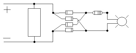
there ya go. the big rectangle on the left is a 40 ohm 5w resistor, the 4 in the center are diodes, and the top right one is a 180ohm 1/2 watt resistor. patent pending :P
 04-25-2006, 10:45 AM
#6
Senior Member
Posts like a Camaro
Thread Starter
Join Date: Oct 2003
Location: Hamilton, Ontario
Posts: 1,074
Likes: 0
Received 0 Likes
on
0 Posts
I hooked it up last night to see what it would look like, the good news, it works perfectly, the bad news, it doesnt make a night and day differance. Its just a single led in the standard light bulb socket. I was expecting more of a differance, but the colour is lighter, and it blinks faster. Now I need to change the front turn signals to led  The pics dont show much but im at a laundromat right now so ill post some when i get home.
04-25-2006, 11:09 AM
#8
Senior Member
True Car Nut

Join Date: Jan 2005
Location: Montevideo, MN MWBF '05, '06, '07 WCBF '06 '07 survivor
Posts: 3,882
Likes: 0
Received 0 Likes
on
0 Posts
Originally Posted by MOS95B
Why the second resistor? Maybe that'* the light/speed issue??
04-25-2006, 11:13 AM
#9
Senior Member
True Car Nut

Join Date: Jun 2004
Location: Rochester, NY (college)
Posts: 6,182
Likes: 0
Received 0 Likes
on
0 Posts
Originally Posted by sonoma_zr2
Originally Posted by MOS95B
Why the second resistor? Maybe that'* the light/speed issue??
04-25-2006, 11:29 AM
#10
Senior Member
Certified Car Nut

Join Date: Jul 2003
Location: Robbinsdale, MN
Posts: 15,408
Likes: 0
Received 0 Likes
on
0 Posts
Originally Posted by corvettecrazy
Originally Posted by sonoma_zr2
Originally Posted by MOS95B
Why the second resistor? Maybe that'* the light/speed issue??
Well, now that you got the circuit worked out, all you gotta do is play with multiple LEDs, or different sizes. The hard part is over....