Wiring a external PNP switch to an internal PNP transmission
 01-07-2011, 07:20 AM
#1
DINOSAURUS BOOSTUS


Expert Gearhead
Thread Starter


I am assuming you are trying to wire your 2000+ Bonneville with internal range selector switch onto a GTP trans that should have an external range selector switch. Sometimes referred to as PRNDL switch.
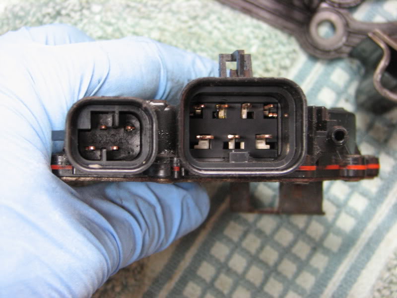
There are 5 wires that need to be worked with, If you look at the back of your main transmission connector it is labeled A through W. Wires F through J are the range selector input wires.
Trans connector
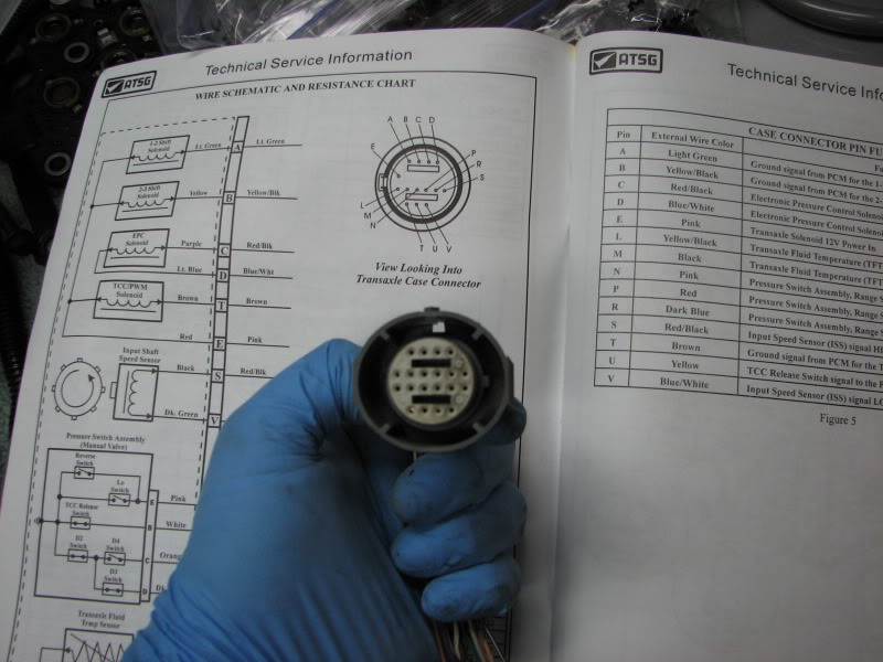
And from the back where the letters are located. The letters are small, be prepared to clean the back of this and look closely
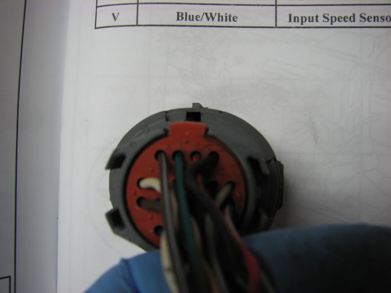
Letters F through J are the ones you want. They should be the middle 4 (of 6) on the third row down. (My picture is of the transmission side, the letters are backwards on this picture.)
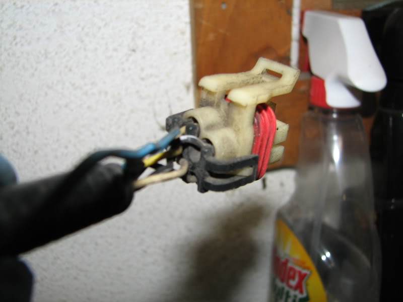
You will connect these four wires to a connector of an external range switch. Here is a picture of an external switch.
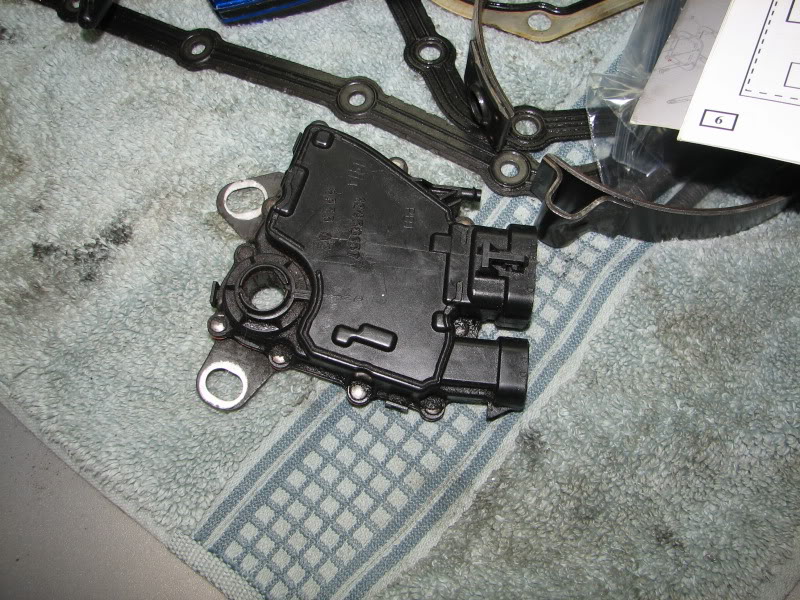
And the four pin connector and the place it connects on the range switch.
From the main trans connector
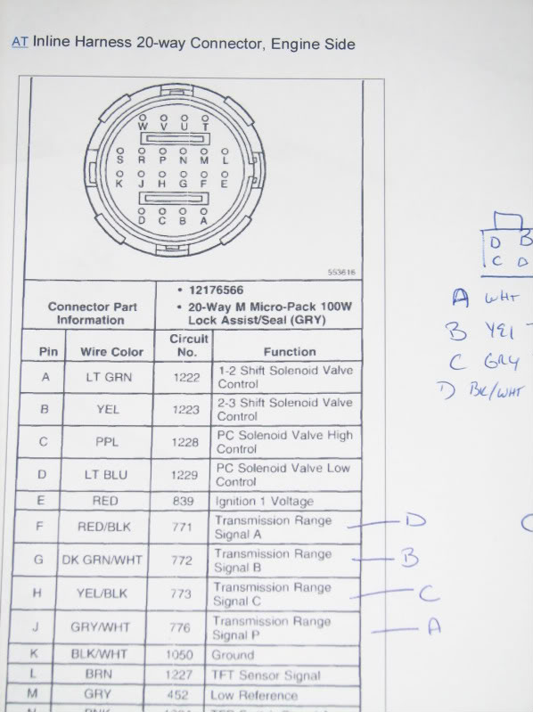
1. Connect wire F which is red with a black trace to wire D on the four pin connector that is black with a white trace.
2. Connect wire G which is dark green with a white trace to wire B on the four pin connector that is yellow.
3. Connect wire H which is yellow with a black trace to wire C on the four pin connector that is gray.
4. Connect wire J which is gray with a white trace to wire D on the four pin connector that is white.
Then connect a ground to pin D of the external range switch (larger) connector. On the 2000+ Bonnevilles there is a ground pack next to the shifter linkage on the transmission that could be tapped into for this connection.
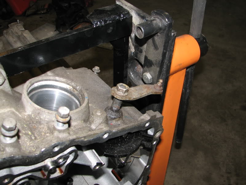
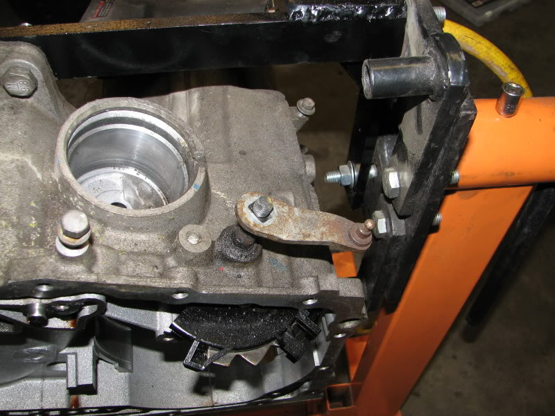
Intall an external range switch on your transmission by removing the 15mm nut holding the selector arm onto the transmission.
Nut on selector lever
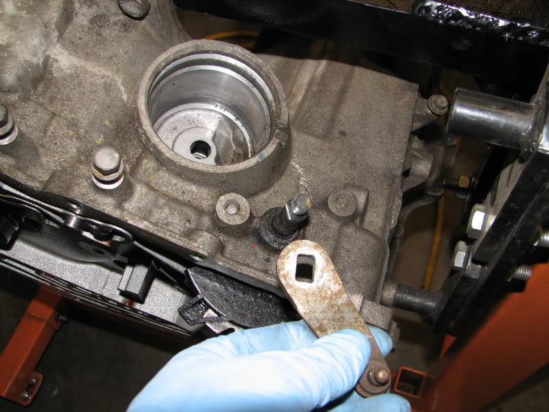
Nut removed
Lift selector lever out of way
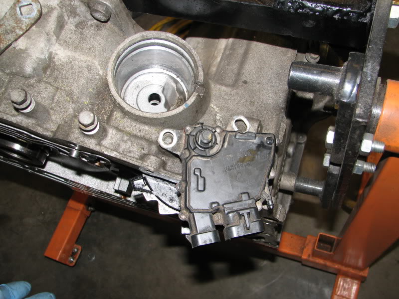
Put switch on trans
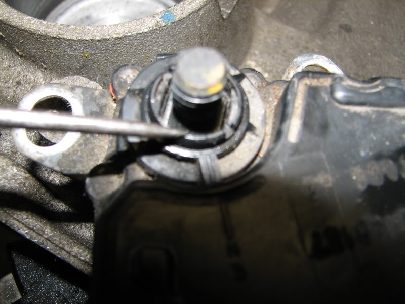
For this to work properly there is a dot on the inner collar by the selector shaft of the trans that must be lined up with a line on the body of the external switch. Dot is being pointed to in the picture
Once these are lined up. Put in the two bolts and tighten. Put the selector arm back in place and the nut that holds it to the shaft, tighten the nut. Connect your two new external range selector connectors and the main trans connector. Turn the car ignition switch to on and review the dash to see that the gear selection is now appearing.
There are 5 wires that need to be worked with, If you look at the back of your main transmission connector it is labeled A through W. Wires F through J are the range selector input wires.
Trans connector
And from the back where the letters are located. The letters are small, be prepared to clean the back of this and look closely
Letters F through J are the ones you want. They should be the middle 4 (of 6) on the third row down. (My picture is of the transmission side, the letters are backwards on this picture.)
You will connect these four wires to a connector of an external range switch. Here is a picture of an external switch.
And the four pin connector and the place it connects on the range switch.
From the main trans connector
1. Connect wire F which is red with a black trace to wire D on the four pin connector that is black with a white trace.
2. Connect wire G which is dark green with a white trace to wire B on the four pin connector that is yellow.
3. Connect wire H which is yellow with a black trace to wire C on the four pin connector that is gray.
4. Connect wire J which is gray with a white trace to wire D on the four pin connector that is white.
Then connect a ground to pin D of the external range switch (larger) connector. On the 2000+ Bonnevilles there is a ground pack next to the shifter linkage on the transmission that could be tapped into for this connection.
Intall an external range switch on your transmission by removing the 15mm nut holding the selector arm onto the transmission.
Nut on selector lever
Nut removed
Lift selector lever out of way
Put switch on trans
For this to work properly there is a dot on the inner collar by the selector shaft of the trans that must be lined up with a line on the body of the external switch. Dot is being pointed to in the picture
Once these are lined up. Put in the two bolts and tighten. Put the selector arm back in place and the nut that holds it to the shaft, tighten the nut. Connect your two new external range selector connectors and the main trans connector. Turn the car ignition switch to on and review the dash to see that the gear selection is now appearing.


Thread
Thread Starter
Forum
Replies
Last Post
BillBoost37
Mechanical
0
01-07-2011 07:20 AM
pk_Harris
Everything Electrical & Electronic
3
08-12-2005 11:12 PM