LED gauge cluster Version 1 complete
 01-29-2012, 09:13 PM
#1
REALLY CONFUSED
Posts like a Turbo
Thread Starter

Join Date: Jan 2010
Location: Vermillion, SD
Posts: 220
Likes: 0
Received 0 Likes
on
0 Posts

First version of my LED dash conversion completed. I say first, because I don't really feel like I am getting satisfactory results from this configuration. The LEDs are slightly dimmer than the incandescent bulbs, so the display is a bit dimmer, with some spots slightly dimmer than others. Therefore, I am going to look into finding something that will give me better results. Surprisingly, I have plenty of room for everything, the only places that space becomes a concern is around the light for the high beams and around the bulbs for the turn signals. Remember, one should be VERY careful with disassembly of the cluster, as you can ruin those motors when you are removing the needles.
There are a total of 8 incandescent micro-bulbs lighting the cluster, and the turn signals and high beam indicator both also use incandescent bulbs. Everything else inside the dash uses colored LEDs. For this conversion, I used 8 neutral white 2 pin LEDs, the brightest ones I had, 2 green, and one blue. One could certainly use only white LEDs, I am just compulsive.
On with the pictures.
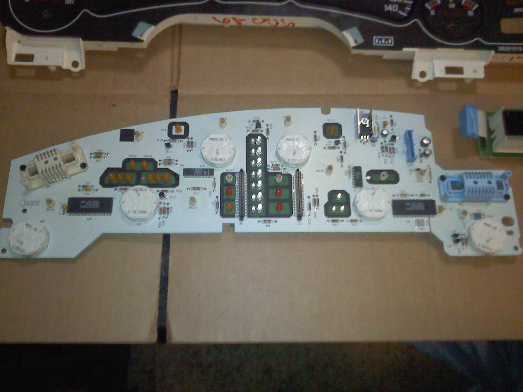
First, you see the main board with the DIC disconnected. You can see all 11 incandescent bulbs, as well as the fact that there are a couple dozen LEDs on the board, begging the question, why did GM put incandescent bulbs in for the turn signal and high beam indicator, but used LEDs for EVERYTHING else? I can only assume that it is some type of easter egg or FU GM put in there, just to tell us that if we ever try and service this part that GM even tells their techs is not serviceable, we deserve some form of disappointment.
I'll spare you the pictures of the board with the bulbs out, and go on to showing you how I configured my LEDs.
Each of the LEDs was set up with a 470 ohm 1/4 watt resistor in series with the light. For the sake of consistency and to make it easier to assemble, I put the resistor on the cathode (negative pole) of all the LEDs. The side you put the resistor on is not important, they just need to all have it on the same end so that you know which side is which. Sorry about the pic, I took them all with my cellphone. You can see I already have one leg bent horizontally.... foreshadowing.
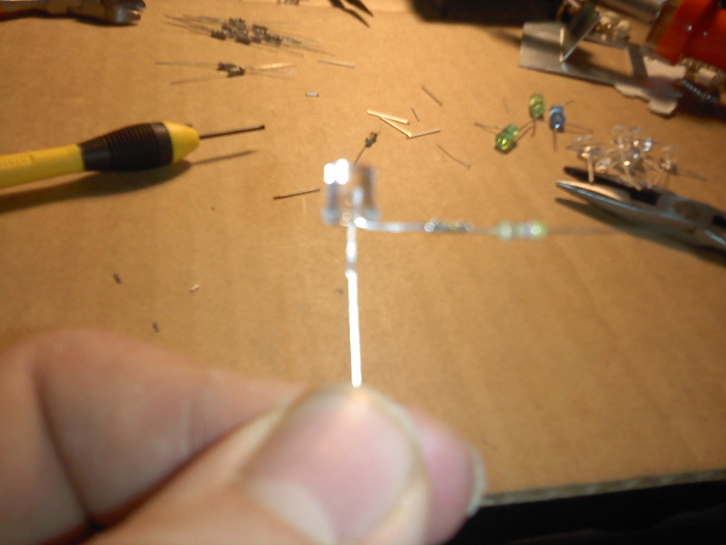
I then added heat-shrink tubing to all the leds between the resistor and the bulb, just to be sure that the part of the cathode before the resistor never shorts with the part after. That would be bad. I then bent the leg around using my iddy-biddy needle nose pliers to form a U-shape horizontally with the bulb, and finally bent the leg after the resistor down to match the original position. You can see my troops below. Note, with my colored LEDs, I bent the legs up and then down, since space is a factor in that configuration, and I don't want any of the light from them to bleed into other parts of the display, or for the light from the other part of the display to bleed in. Therefore, I couldn't cut any type of relief slot to accommodate the resistors in a horizontal position. This positioning doesn't cause any problem. In fact, these are the one thing in this display that I find myself satisfied with.

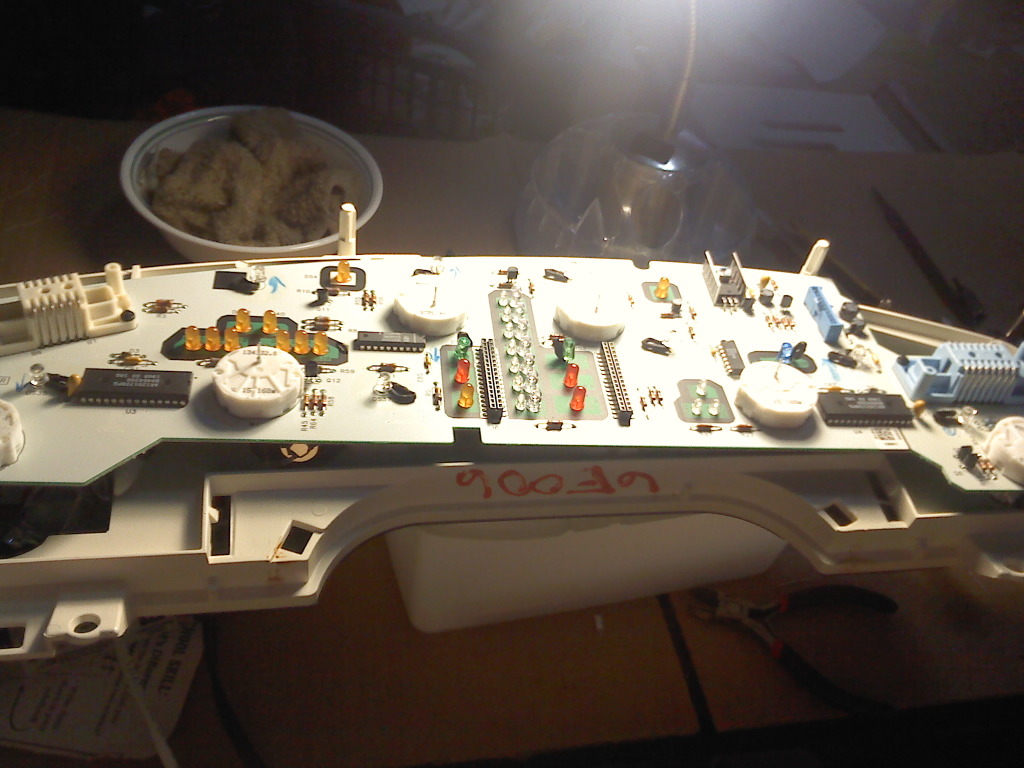
Now you see the board fully populated with LEDs, ignore the little arrows, I drew them on there to mark polarity. I forgot to write it all down, so you will have to get it from me at a later date, or test using an ohmmeter when you have all the old bulbs out. On the connector marked J2 on this board, power for the lights comes in on pin B8, and the ground is on pin A2. With this information in hand, you should have no problem finding the correct polarity. For the turn signals, the anode faces down, for the high beam up.
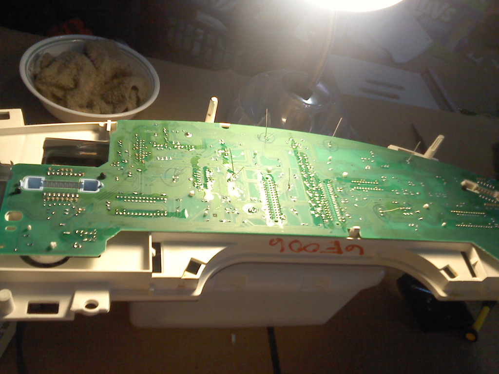
Here you have the back of the board with everything soldered. Those leads get cut off after you are all done, they are left on during soldering so that they can be bent to hold the LED to the board when you flip it over. If you are not good at soldering, please practice on something cheaper that the destruction of won't make driving your Bonneville impossible.
Reassemble and enjoy.... though, hopefully you have found a better LED than the ones I used. I am not going to include a picture of what the display looks like after replacement of the bulbs, since the camera exaggerates the hot and dim spots WAY too much to give you a realistic idea of what they look like. Sometime in the near future, I will be trying this project with a different LED. This does reduce power consumption by quite a bit, and IMO is a worthwhile project if you have bulbs out anyway. Changing color of the display will be nearly impossible using this method however. The face of the cluster is glued onto the portion of the cluster the board fits into, and the coloration is achieved through printing onto the back of the face. One could remove the face (hopefully without destroying it), remove all the glue, clear off the old color, color it the way you want it to look, then finally glue it back down, but I wouldn't recommend it. At best, you can use bright colored LEDs behind the display, but you will have to accept that it will still have a red tint.
I'll get back to you all later with my conversion of the stereo, and you can bet I will be swapping incandescent bulbs out of the other switches that use them. Feel free to ask questions.
There are a total of 8 incandescent micro-bulbs lighting the cluster, and the turn signals and high beam indicator both also use incandescent bulbs. Everything else inside the dash uses colored LEDs. For this conversion, I used 8 neutral white 2 pin LEDs, the brightest ones I had, 2 green, and one blue. One could certainly use only white LEDs, I am just compulsive.
On with the pictures.
First, you see the main board with the DIC disconnected. You can see all 11 incandescent bulbs, as well as the fact that there are a couple dozen LEDs on the board, begging the question, why did GM put incandescent bulbs in for the turn signal and high beam indicator, but used LEDs for EVERYTHING else? I can only assume that it is some type of easter egg or FU GM put in there, just to tell us that if we ever try and service this part that GM even tells their techs is not serviceable, we deserve some form of disappointment.
I'll spare you the pictures of the board with the bulbs out, and go on to showing you how I configured my LEDs.
Each of the LEDs was set up with a 470 ohm 1/4 watt resistor in series with the light. For the sake of consistency and to make it easier to assemble, I put the resistor on the cathode (negative pole) of all the LEDs. The side you put the resistor on is not important, they just need to all have it on the same end so that you know which side is which. Sorry about the pic, I took them all with my cellphone. You can see I already have one leg bent horizontally.... foreshadowing.
I then added heat-shrink tubing to all the leds between the resistor and the bulb, just to be sure that the part of the cathode before the resistor never shorts with the part after. That would be bad. I then bent the leg around using my iddy-biddy needle nose pliers to form a U-shape horizontally with the bulb, and finally bent the leg after the resistor down to match the original position. You can see my troops below. Note, with my colored LEDs, I bent the legs up and then down, since space is a factor in that configuration, and I don't want any of the light from them to bleed into other parts of the display, or for the light from the other part of the display to bleed in. Therefore, I couldn't cut any type of relief slot to accommodate the resistors in a horizontal position. This positioning doesn't cause any problem. In fact, these are the one thing in this display that I find myself satisfied with.
Now you see the board fully populated with LEDs, ignore the little arrows, I drew them on there to mark polarity. I forgot to write it all down, so you will have to get it from me at a later date, or test using an ohmmeter when you have all the old bulbs out. On the connector marked J2 on this board, power for the lights comes in on pin B8, and the ground is on pin A2. With this information in hand, you should have no problem finding the correct polarity. For the turn signals, the anode faces down, for the high beam up.
Here you have the back of the board with everything soldered. Those leads get cut off after you are all done, they are left on during soldering so that they can be bent to hold the LED to the board when you flip it over. If you are not good at soldering, please practice on something cheaper that the destruction of won't make driving your Bonneville impossible.
Reassemble and enjoy.... though, hopefully you have found a better LED than the ones I used. I am not going to include a picture of what the display looks like after replacement of the bulbs, since the camera exaggerates the hot and dim spots WAY too much to give you a realistic idea of what they look like. Sometime in the near future, I will be trying this project with a different LED. This does reduce power consumption by quite a bit, and IMO is a worthwhile project if you have bulbs out anyway. Changing color of the display will be nearly impossible using this method however. The face of the cluster is glued onto the portion of the cluster the board fits into, and the coloration is achieved through printing onto the back of the face. One could remove the face (hopefully without destroying it), remove all the glue, clear off the old color, color it the way you want it to look, then finally glue it back down, but I wouldn't recommend it. At best, you can use bright colored LEDs behind the display, but you will have to accept that it will still have a red tint.
I'll get back to you all later with my conversion of the stereo, and you can bet I will be swapping incandescent bulbs out of the other switches that use them. Feel free to ask questions.


Thread
Thread Starter
Forum
Replies
Last Post