Toasted resistors in heater actuator--(2002 Bonneville)
 11-19-2007, 11:06 AM
#1
Member
Posts like a V-Tak
Thread Starter

Join Date: Nov 2007
Location: Delaware, OH
Posts: 38
Likes: 0
Received 0 Likes
on
0 Posts

I have a bad heater actuator. (it'* the one that allows air to flow over the heater core)
R8 and R9 are toast. I contacted the manufacturer in Tennesee and they gave me the resistor values so I could repair it. It turns out they were supposed to be 1 watt resistors, but my circuit board had been manufactured with 1/4 watt resistors, which explains why they didn't last. (I'm surprised they held up as long as they did !!!)
Mine can't be the only one built wrong. Anyone else seen this?
 11-19-2007, 11:17 AM
#2
DINOSAURUS BOOSTUS


Expert Gearhead

Most would change the actuator assuming it bad.
Can you post up some pics and general info on how you chose to diagnose it. That would be helpful to many others. Afterall.. a $3 fix vs $30 or so is much nicer.
Can you post up some pics and general info on how you chose to diagnose it. That would be helpful to many others. Afterall.. a $3 fix vs $30 or so is much nicer.
11-19-2007, 12:30 PM
#3
Member
Posts like a V-Tak
Thread Starter
Join Date: Nov 2007
Location: Delaware, OH
Posts: 38
Likes: 0
Received 0 Likes
on
0 Posts
How the heck do you insert a photo in here? If I click on Img, all it does is add "[img]" to the text...
Anyway, the troubleshooting process went like this:
After determining the actuator was faulty, I opened it up out of curiousity (since the GM and extended warranties had expired and were not an issue) and found the burned resistors. I couldn't determine their value because the color bands had been dis-colored by heat, so I searched out the mfg and called them to get the values for R8 and R9. (The component designators were painted on the component side) They said they'd get back with me.
After waiting about a week, I had whimped out and bought a new actuator cuz it was getting cold here in Ohio. Right after that (of course) they emailed me the info.
R8 and R9 were supposed to be 10 ohms at 1 watt. I knew mine were not 1 watt by their physical size, but figured the heftier wattage was the result of a subsequent engineering change.
I decided to attempt to repair the bad one anyway (I had the resistors in my junque box) so I'd have a spare. When I looked closer at the circuit board, I noticed that the painted outlines for R8 and R9 were much larger than for the other resistors on the board (all others were 1/4 watt). That is what tipped me off that R8 and R9 should have been 1-watters from the git-go. I now have an email into the mfg to see how they take the news of my discovery. The repair is on-hold pending their reply.
If someone does attempt to repair one of these actuators for this same failure, be prepared to also repair the circuit-side of the board, because you may find the tracks near the resistors in question have been burned off the board. Also, you'll have to re-sync the output gear of the actuator with the gear on the feedback potentiometer on the circuit board. (I have instructions from the mfg on how to do this--(looks very simple)
I'll send photos after I learn how to do it. Later, Joe
11-19-2007, 12:31 PM
#4
BANNED

Join Date: Mar 2004
Location: Purgatory
Posts: 0
Likes: 0
Received 0 Likes
on
0 Posts
11-19-2007, 12:56 PM
#5
Member
Posts like a V-Tak
Thread Starter
Join Date: Nov 2007
Location: Delaware, OH
Posts: 38
Likes: 0
Received 0 Likes
on
0 Posts
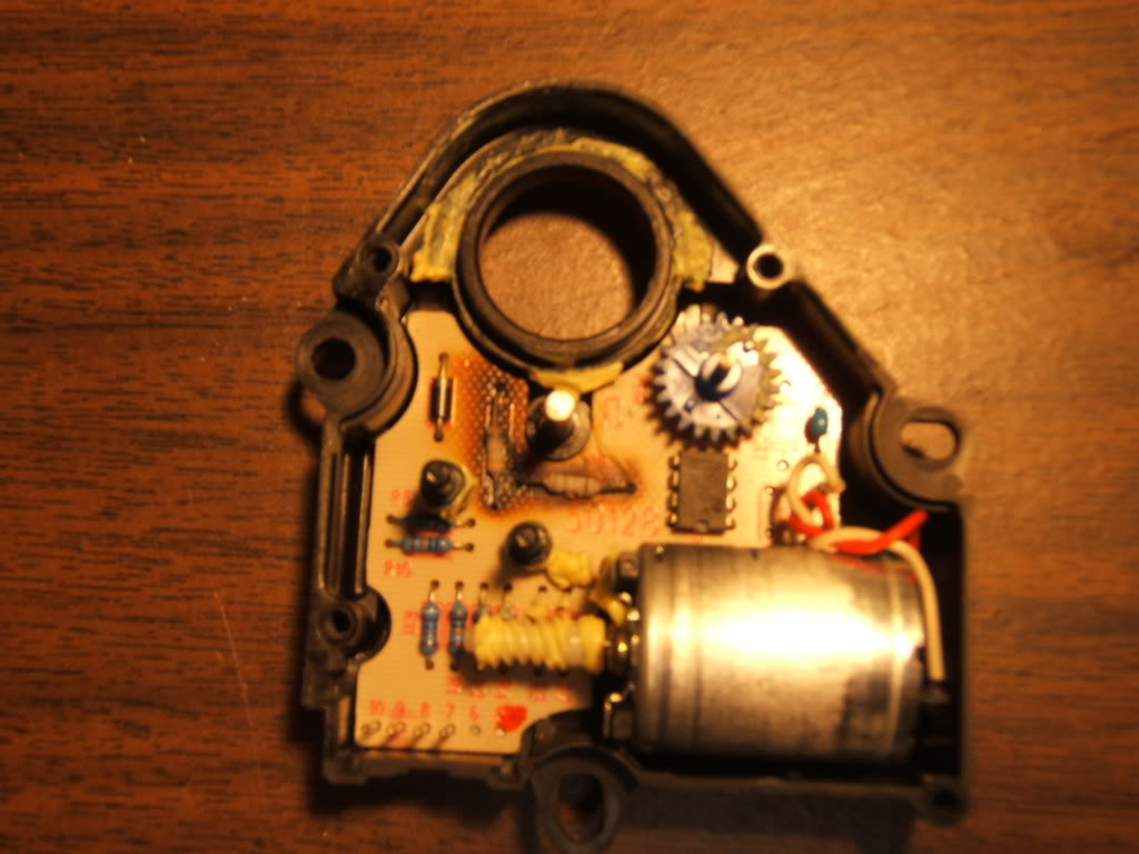
The gears have been removed so you can see R8 and R9. If you look closely, you can see the larger painted outlines for those two resistors.

 11-26-2007, 10:13 AM
#9
Member
Posts like a V-Tak
Thread Starter
Join Date: Nov 2007
Location: Delaware, OH
Posts: 38
Likes: 0
Received 0 Likes
on
0 Posts
Guys,
Sorry it took me so long to post this. (You know how 4-day weekends can be)
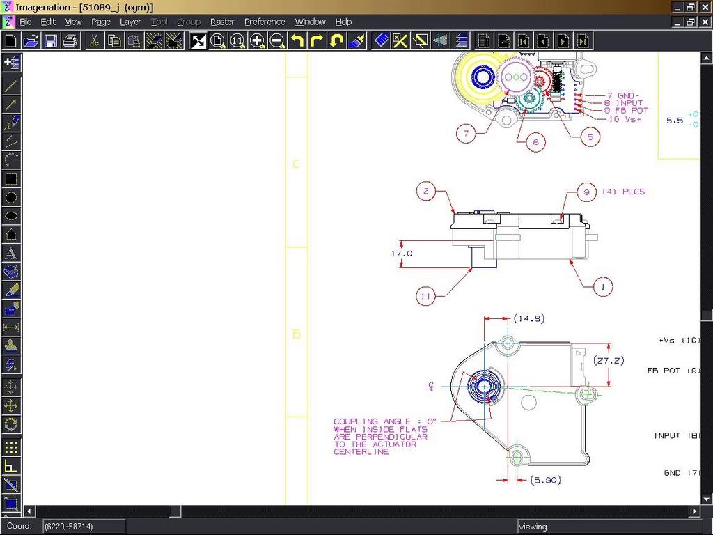
CIE (aka Saia-Burgess Automotive Actuators, Inc and aka Johnson Actuators) didn't send me an electronic schemtic. They only sent the blueprint of part of the actuator with quickie instructions on re-syncing the output gear with the pot. (It appears that he took a screen-shot of his CAD application)
The image does show the pin-out for the circuit board, which could be helpful when trouble shooting.
Later, Joe
Here is the text of his email and the screen-shot:
Hi Joe:
The two resistors (R8 and R9) are both 10 ohms, 1 watt. to set the
potentiometer, rotate it so its resistance between pins 9 and 10 of the
board reads about 5 kohms (mid point of this 10 kohm pot), then insert the
big (output) gear so the coupling is at 0�. Board pin-out and definition
of home position (output coupling at 0�) are included below. Since this
product is old, I can't warranty you that these values will work with your
actuator. Good luck
Sorry it took me so long to post this. (You know how 4-day weekends can be)
CIE (aka Saia-Burgess Automotive Actuators, Inc and aka Johnson Actuators) didn't send me an electronic schemtic. They only sent the blueprint of part of the actuator with quickie instructions on re-syncing the output gear with the pot. (It appears that he took a screen-shot of his CAD application)
The image does show the pin-out for the circuit board, which could be helpful when trouble shooting.
Later, Joe
Here is the text of his email and the screen-shot:
Hi Joe:
The two resistors (R8 and R9) are both 10 ohms, 1 watt. to set the
potentiometer, rotate it so its resistance between pins 9 and 10 of the
board reads about 5 kohms (mid point of this 10 kohm pot), then insert the
big (output) gear so the coupling is at 0�. Board pin-out and definition
of home position (output coupling at 0�) are included below. Since this
product is old, I can't warranty you that these values will work with your
actuator. Good luck