Build your own engine hanger for trans removal
 01-15-2005, 11:00 AM
#1
Senior Member
True Car Nut
Thread Starter

If some of you are like me, with the weather so crummy, you may be looking for a winter project that has something to do with your Bonneville, where you can spend a few hours in the shop. Here are plans for building the engine hanger I am using to replace the trans in my '95 SLE.
I was gonna submit this to techinfo, but there are no illustrations in techinfo, and they really help visualize what you need to do. Aplologizing in advance for drawings where perpendicular and square aren't quite perpendicular and square...Here' * the file:
ENGINE HANGER FOR 95 Bonneville L36
This hanger is used to support and slightly raise the engine and transmission and hold in position to allow replacement of the transmission from below. This hanger was designed to sit as close to the engine as possible, allowing the hood to almost close. Only simple hand tools and skills are required, there are no welds. All components are fastened by grade 5 and grade 8 bolts and nuts. The hanger can be disassembled for compact storage or shipping. The unit has been tested and performed well with no visible distortion or movement under load, and no damage observed on the load bearing surfaces.
Measurements given are for a �95 Bonneville L36, but may not be correct for your car owing to differences in positioning of motor lifting rings, condition and placement of motor mounts and strut mounts. Best fit will be obtained if measurements for locating the beams and lifting shackles are made in place on your car. Use oil to keep your drill bits lubricated and cool as they cut and use slower speeds for larger drills. Drilling an 1/8� pilot hole first, then increasing to the final hole size will make things go more easily. Hand-fit brackets are not likely to interchange, so mark each bracket and its orientation with paint, metal stamps, or otherwise to aid in assembly for future use. The method described for fabrication is slow due to the need to repeatedly disassemble and reassemble parts, but will produce good results with a minimum of measuring and machining skills (a necessity in my case!)
Materials: 6-ft length of 3/16-inch wall 1-1/2� square tubing
3-ft length of 3/16-inch thick 1-1/2� angle iron
3-inch length of heavy wall (1/4�) 2� x 3� rectangular tubing
12- grade 8 extra thick (0.114� ) 3/8" USS washers
2- grade 5, 3/8�-16 x 4� full thread tap bolts and nuts
2- grade 5, 3/8�-16 x 2-1/2� hex head cap screws and nuts
4- grade 5, 5/16�-18 x 1� hex head cap screws and nuts
7- grade 8, 5/16�-18 x 3/4� hex head cap screws
Approximate cost: (January, 2005) $35
Time required to build: Two easy days (10 hrs)
Tools: good hacksaw with new bi-metal blade
vise (4� minimum jaw spread)
3/8� electric drill or drill press
center punch, scribe, metal marker
file or grinder
5/16� x 18 tap and handle
1/8�,1/4�, 5/16�, 11/32�, and 3/8� drill bits
cutting oil, tapping oil
carpenter�* square
wide measuring tape
Metal cutting: Except for front beam joint and shackle bolt holes, all cuts are made square, and holes drilled perpendicular.
From the 3-foot piece of angle: cut 6) 1-1/2� pieces for brackets; and 2) 7-1/4� pieces for shelves, leaving a piece about a foot long for the front beam support that will rest in front of the top radiator support.
On the 3-inch piece of 2 x 3, make two longitudinal cuts to remove one 2� side to give a �U� shaped cross section. Then cross-cut into two identical 1-1/2�, �U�-shaped pieces for the frames of the lifting shackles.
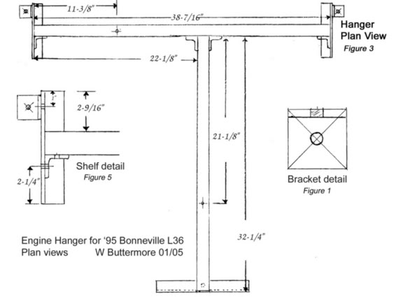
Brackets: Scribe an X from corner to corner on the outside of each of the six 1-1/2� pieces of angle iron. Center punch the center of the X. Drill to 11/32�; 12 holes total. (Figure 1)
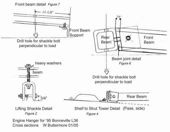
Lifting Shackles: Drill a 3/8� hole in the center of each 1-1/2� x 2� top side for the 3/8� lifting screw. Drill a 3/8� hole across the legs of the shackle centered in each side and about 3/4" from the bottom of each leg. Keep this �through hole� as perpendicular to the sides as possible. (Figure 2)
Preliminary work: Remove the relay center cover, engine cover, top radiator support and fan bolts, hood latch and spring. It is not necessary to remove the hood release cable from the latch. Remove the nuts from the two inside studs on each strut, and remove the strut support. Install a heavy washer and nut on the front strut studs and tighten to about 20 ft-lbs.
Rear Shelves: Place two thick washers over each rear stud, then place a bracket on each stud with the vertical leg facing inward (toward each other). This will make the driver�* side strut bracket appear like the letter �L� when viewed from the front of the car. Place a washer and nut on each bracket and tighten the nut so the bracket can still be rotated with some effort. Place the shelf pieces on the strut towers so they are parallel with each other and so that the vertical leg of each shelf piece lays flat against its strut bracket, forming an upside-down �T�. This will make the passenger side shelf appear like the letter �L� when viewed from the front. The purpose of the shelf is to distribute the weight from the rear beam as evenly as practicable over the top of the strut tower. The shelf brackets only hold the shelf in position, to prevent the assembly from moving under load. When fastened, the shelf pieces will not be perfectly flat but will tilt down toward each other when viewed from the front of the car. (Figure 4) If necessary, shim or modify the attachment so the shelves lay evenly against the top of the strut towers. Mark the shelf pieces using the hole in the strut bracket so that the center of the hole is about 1-inch from the rear end of each shelf piece. (Figure 5) Remove the shelf pieces and drill 5/16� holes on the marks. Return the shelf pieces to the car, loosen the shelf brackets, then align the shelves parallel, and attach and tighten the shelves and brackets in place with bolts and nuts. Measure the opening between the shelf pieces at both ends to make sure they are nearly parallel.
Rear Beam: Using a tape measure, locate the position on the shelves where the beam will sit in front of the master cylinder reservoir, and directly over the rear lifting ring on the engine. Measure the distance between the vertical legs of the shelves at that point, and cut the square tube to that length. For my car, the length of the rear beam is 38-7/16�. (Figure 3) Place the beam on the shelves in the correct position, and mark the shelves. For my car, the rear edge of the beam was 1-9/16� forward of the center of the rear strut stud. (Figure 5) Position the beam-locating brackets with one of the flats against the vertical leg of the shelf and the other flat against the front side of the beam. Grind or file the bottom edge of the two brackets to fit tightly against the web of the shelf pieces. Using the bracket hole as a guide, mark holes to be drilled in the vertical leg of each shelf. Remove the shelves and drill for 5/16� through-bolts and nuts. Reassemble the shelves, place the beam in position, and with the beam-locating brackets flat against the shelf and the beam, bolt the brackets to the shelves and mark the rear beam using the holes in the brackets. Remove the beam, drill 1/4� holes on the marks and tap to 5/16�-18. Install the rear beam with grade 8, 5/16" bolts.
Front Beam: Cut one end of the remaining piece of square tubing at about a 10 degree angle such that the top side of the beam is 1/4� shorter than the bottom. (Figure 6) This will compensate for the angle between the beams at the junction of the �T� when the hanger is assembled. For my car, the top of the front beam measures 32-1/4". Position the front beam so that it is square with the rear beam and centered over the front lifting ring on the engine. On my car, the passenger�* side of the front beam is located a distance 22-1/8� from the passenger�* end of the rear beam. Use a shim on the engine to support the front beam in place, and check to make sure the length will put the front beam support in a good place. The front beam support is positioned with one outside flat against the bottom side of the front beam, and the other flat flush with the end of the beam. (Figure 7) The support should rest on its edge on the metal piece in front of the hood latch. Drill a 5/16� hole in the front beam support piece approximately in the center of its length and 3/4� from an edge. Use the hole to mark the bottom of the front beam. Drill and tap the front beam for a 5/16" bolt and attach the front beam support. With the front beam support attached and using the shim, place the front beam in position against the rear beam. Position the two remaining brackets so that the holes are as close to the center of both beams as possible. The holes for the brackets will be below center on the rear beam and above center on the front beam. (Figure 6) Because of the angle at the point of attachment, the top edge of the brackets will protrude above the front beam. Using the brackets, mark the holes on the front beam. Remove the beam and drill and tap the holes. Attach the brackets to the front beam; re-align the beams and brackets to mark the holes on the rear beam. Remove the rear beam and drill and tap the holes. Assemble the beams. If you like, grind or cut off the protruding metal on the brackets.
Holes for Lifting Shackles: With the beams assembled and in place, use a plumb bob, or a small weight on a string to locate the marks on the beams where the holes will be drilled for the lifting shackles to sit directly above the lifting rings. For my car, the hole for the rear shackle is on a line 11-3/8� from the passenger�* end of the rear beam; the center of the hole for the front shackle is 21-1/8� measured along the top of the front beam from the front side of the rear beam. (Figure 3) Notice that neither beam is parallel to the ground. In order for the lifting shackles to be perpendicular to the load they will carry, it is necessary to drill the holes through the beams at a small angle. For the rear beam, the hole in the top is offset about 1/8� or less toward the front and the hole in the bottom is offset about the same to the rear. (Figure 6) For the front beam, the hole in the top is offset to the rear, and the hole in the bottom is offset to the front. (Figure 7) The angle for the hole in the front beam can be easily marked with a plumb bob.
Lifting Shackles: Assemble the lifting shackles by installing a 2-1/2" x 3/8" grade 5 bolt across the legs and securing with a nut. Install two heavy washers on top of the beam, and one heavy washer and nut under the top hole of the shackle. (Figure 2) Depending on what you use to attach the shackle to the engine lifting rings, you will probably need to adjust the length of the lifting bolt to provide the greatest amount of lift. I used two chain quick links in the back and a forged steel shackle in the front. The rear bolt was used as-is, 4�-long, the front bolt was cut down to about 3-1/4�
Picture of the hanger in use here: http://bonnevilleclub.com/forum/view...558&highlight=
Here is what it looks like when disassembled and ready for shipping or storage:
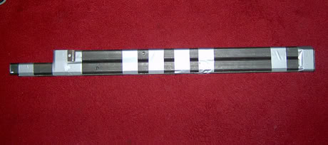
This weighs about 22 pounds and measures 3.25 x 39 x 2 inches. The fasteners are stored inside one of the beams.
I was gonna submit this to techinfo, but there are no illustrations in techinfo, and they really help visualize what you need to do. Aplologizing in advance for drawings where perpendicular and square aren't quite perpendicular and square...Here' * the file:
ENGINE HANGER FOR 95 Bonneville L36
This hanger is used to support and slightly raise the engine and transmission and hold in position to allow replacement of the transmission from below. This hanger was designed to sit as close to the engine as possible, allowing the hood to almost close. Only simple hand tools and skills are required, there are no welds. All components are fastened by grade 5 and grade 8 bolts and nuts. The hanger can be disassembled for compact storage or shipping. The unit has been tested and performed well with no visible distortion or movement under load, and no damage observed on the load bearing surfaces.
Measurements given are for a �95 Bonneville L36, but may not be correct for your car owing to differences in positioning of motor lifting rings, condition and placement of motor mounts and strut mounts. Best fit will be obtained if measurements for locating the beams and lifting shackles are made in place on your car. Use oil to keep your drill bits lubricated and cool as they cut and use slower speeds for larger drills. Drilling an 1/8� pilot hole first, then increasing to the final hole size will make things go more easily. Hand-fit brackets are not likely to interchange, so mark each bracket and its orientation with paint, metal stamps, or otherwise to aid in assembly for future use. The method described for fabrication is slow due to the need to repeatedly disassemble and reassemble parts, but will produce good results with a minimum of measuring and machining skills (a necessity in my case!)
Materials: 6-ft length of 3/16-inch wall 1-1/2� square tubing
3-ft length of 3/16-inch thick 1-1/2� angle iron
3-inch length of heavy wall (1/4�) 2� x 3� rectangular tubing
12- grade 8 extra thick (0.114� ) 3/8" USS washers
2- grade 5, 3/8�-16 x 4� full thread tap bolts and nuts
2- grade 5, 3/8�-16 x 2-1/2� hex head cap screws and nuts
4- grade 5, 5/16�-18 x 1� hex head cap screws and nuts
7- grade 8, 5/16�-18 x 3/4� hex head cap screws
Approximate cost: (January, 2005) $35
Time required to build: Two easy days (10 hrs)
Tools: good hacksaw with new bi-metal blade
vise (4� minimum jaw spread)
3/8� electric drill or drill press
center punch, scribe, metal marker
file or grinder
5/16� x 18 tap and handle
1/8�,1/4�, 5/16�, 11/32�, and 3/8� drill bits
cutting oil, tapping oil
carpenter�* square
wide measuring tape
Metal cutting: Except for front beam joint and shackle bolt holes, all cuts are made square, and holes drilled perpendicular.
From the 3-foot piece of angle: cut 6) 1-1/2� pieces for brackets; and 2) 7-1/4� pieces for shelves, leaving a piece about a foot long for the front beam support that will rest in front of the top radiator support.
On the 3-inch piece of 2 x 3, make two longitudinal cuts to remove one 2� side to give a �U� shaped cross section. Then cross-cut into two identical 1-1/2�, �U�-shaped pieces for the frames of the lifting shackles.
Brackets: Scribe an X from corner to corner on the outside of each of the six 1-1/2� pieces of angle iron. Center punch the center of the X. Drill to 11/32�; 12 holes total. (Figure 1)
Lifting Shackles: Drill a 3/8� hole in the center of each 1-1/2� x 2� top side for the 3/8� lifting screw. Drill a 3/8� hole across the legs of the shackle centered in each side and about 3/4" from the bottom of each leg. Keep this �through hole� as perpendicular to the sides as possible. (Figure 2)
Preliminary work: Remove the relay center cover, engine cover, top radiator support and fan bolts, hood latch and spring. It is not necessary to remove the hood release cable from the latch. Remove the nuts from the two inside studs on each strut, and remove the strut support. Install a heavy washer and nut on the front strut studs and tighten to about 20 ft-lbs.
Rear Shelves: Place two thick washers over each rear stud, then place a bracket on each stud with the vertical leg facing inward (toward each other). This will make the driver�* side strut bracket appear like the letter �L� when viewed from the front of the car. Place a washer and nut on each bracket and tighten the nut so the bracket can still be rotated with some effort. Place the shelf pieces on the strut towers so they are parallel with each other and so that the vertical leg of each shelf piece lays flat against its strut bracket, forming an upside-down �T�. This will make the passenger side shelf appear like the letter �L� when viewed from the front. The purpose of the shelf is to distribute the weight from the rear beam as evenly as practicable over the top of the strut tower. The shelf brackets only hold the shelf in position, to prevent the assembly from moving under load. When fastened, the shelf pieces will not be perfectly flat but will tilt down toward each other when viewed from the front of the car. (Figure 4) If necessary, shim or modify the attachment so the shelves lay evenly against the top of the strut towers. Mark the shelf pieces using the hole in the strut bracket so that the center of the hole is about 1-inch from the rear end of each shelf piece. (Figure 5) Remove the shelf pieces and drill 5/16� holes on the marks. Return the shelf pieces to the car, loosen the shelf brackets, then align the shelves parallel, and attach and tighten the shelves and brackets in place with bolts and nuts. Measure the opening between the shelf pieces at both ends to make sure they are nearly parallel.
Rear Beam: Using a tape measure, locate the position on the shelves where the beam will sit in front of the master cylinder reservoir, and directly over the rear lifting ring on the engine. Measure the distance between the vertical legs of the shelves at that point, and cut the square tube to that length. For my car, the length of the rear beam is 38-7/16�. (Figure 3) Place the beam on the shelves in the correct position, and mark the shelves. For my car, the rear edge of the beam was 1-9/16� forward of the center of the rear strut stud. (Figure 5) Position the beam-locating brackets with one of the flats against the vertical leg of the shelf and the other flat against the front side of the beam. Grind or file the bottom edge of the two brackets to fit tightly against the web of the shelf pieces. Using the bracket hole as a guide, mark holes to be drilled in the vertical leg of each shelf. Remove the shelves and drill for 5/16� through-bolts and nuts. Reassemble the shelves, place the beam in position, and with the beam-locating brackets flat against the shelf and the beam, bolt the brackets to the shelves and mark the rear beam using the holes in the brackets. Remove the beam, drill 1/4� holes on the marks and tap to 5/16�-18. Install the rear beam with grade 8, 5/16" bolts.
Front Beam: Cut one end of the remaining piece of square tubing at about a 10 degree angle such that the top side of the beam is 1/4� shorter than the bottom. (Figure 6) This will compensate for the angle between the beams at the junction of the �T� when the hanger is assembled. For my car, the top of the front beam measures 32-1/4". Position the front beam so that it is square with the rear beam and centered over the front lifting ring on the engine. On my car, the passenger�* side of the front beam is located a distance 22-1/8� from the passenger�* end of the rear beam. Use a shim on the engine to support the front beam in place, and check to make sure the length will put the front beam support in a good place. The front beam support is positioned with one outside flat against the bottom side of the front beam, and the other flat flush with the end of the beam. (Figure 7) The support should rest on its edge on the metal piece in front of the hood latch. Drill a 5/16� hole in the front beam support piece approximately in the center of its length and 3/4� from an edge. Use the hole to mark the bottom of the front beam. Drill and tap the front beam for a 5/16" bolt and attach the front beam support. With the front beam support attached and using the shim, place the front beam in position against the rear beam. Position the two remaining brackets so that the holes are as close to the center of both beams as possible. The holes for the brackets will be below center on the rear beam and above center on the front beam. (Figure 6) Because of the angle at the point of attachment, the top edge of the brackets will protrude above the front beam. Using the brackets, mark the holes on the front beam. Remove the beam and drill and tap the holes. Attach the brackets to the front beam; re-align the beams and brackets to mark the holes on the rear beam. Remove the rear beam and drill and tap the holes. Assemble the beams. If you like, grind or cut off the protruding metal on the brackets.
Holes for Lifting Shackles: With the beams assembled and in place, use a plumb bob, or a small weight on a string to locate the marks on the beams where the holes will be drilled for the lifting shackles to sit directly above the lifting rings. For my car, the hole for the rear shackle is on a line 11-3/8� from the passenger�* end of the rear beam; the center of the hole for the front shackle is 21-1/8� measured along the top of the front beam from the front side of the rear beam. (Figure 3) Notice that neither beam is parallel to the ground. In order for the lifting shackles to be perpendicular to the load they will carry, it is necessary to drill the holes through the beams at a small angle. For the rear beam, the hole in the top is offset about 1/8� or less toward the front and the hole in the bottom is offset about the same to the rear. (Figure 6) For the front beam, the hole in the top is offset to the rear, and the hole in the bottom is offset to the front. (Figure 7) The angle for the hole in the front beam can be easily marked with a plumb bob.
Lifting Shackles: Assemble the lifting shackles by installing a 2-1/2" x 3/8" grade 5 bolt across the legs and securing with a nut. Install two heavy washers on top of the beam, and one heavy washer and nut under the top hole of the shackle. (Figure 2) Depending on what you use to attach the shackle to the engine lifting rings, you will probably need to adjust the length of the lifting bolt to provide the greatest amount of lift. I used two chain quick links in the back and a forged steel shackle in the front. The rear bolt was used as-is, 4�-long, the front bolt was cut down to about 3-1/4�
Picture of the hanger in use here: http://bonnevilleclub.com/forum/view...558&highlight=
Here is what it looks like when disassembled and ready for shipping or storage:
This weighs about 22 pounds and measures 3.25 x 39 x 2 inches. The fasteners are stored inside one of the beams.

 01-15-2005, 05:21 PM
#3
Senior Member
Posts like a Camaro

Join Date: Jul 2004
Location: Manassas, Virginia NOVA
Posts: 827
Likes: 0
Received 0 Likes
on
0 Posts

Without reading all of that stuff would this mean that one could take off the engine mounts to do maintenance on things that are blocked by the mounts without having to put a jack underneath the engine?
01-15-2005, 09:24 PM
#4
Senior Member
True Car Nut
Thread Starter
Originally Posted by CmptrNerd
Without reading all of that stuff would this mean that one could take off the engine mounts to do maintenance on things that are blocked by the mounts without having to put a jack underneath the engine?

Thread
Thread Starter
Forum
Replies
Last Post
Dirthead Racing
Performance, Brainstorming & Tuning
15
08-07-2006 06:30 PM
Kill4Nuggs
Performance, Brainstorming & Tuning
9
01-25-2006 09:27 AM